Home › Vehicle Exterior › WIPER / WASHER › WIPER AND WASHER SYSTEM
RM19V0EQ _59 Vehicle Exterior _014620 WIPER / WASHER _0074239 WIPER AND WASHER SYSTEM J

WIPER / WASHER  WIPER AND WASHER SYSTEM  Front Wiper Motor Circuit  


DESCRIPTION

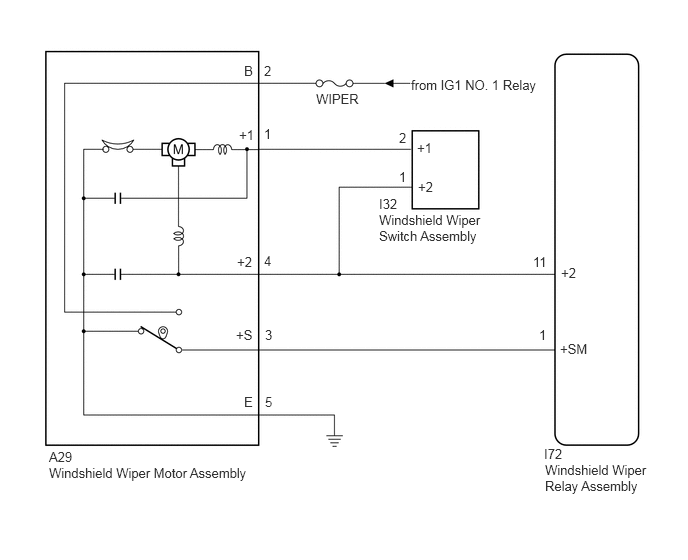
The windshield wiper relay assembly controls the windshield wiper motor assembly.

WIRING DIAGRAM
E227682E09
0.51,4.677 1.031,4.979 0.521,0.302 10 false A29 0.51,4.844 2.708,5.031 2.198,0.188 10 false Windshield Wiper Motor Assembly 5.667,4.646 6.094,4.906 0.427,0.26 10 false I72 5.677,4.813 6.813,5.333 1.135,0.521 10 false Windshield Wiper Relay Assembly 3.292,0.948 4.146,1.292 0.854,0.344 10 false WIPER 4.281,0.802 5.729,1 1.448,0.198 10 false from IG1 NO. 1 Relay 5.844,2.76 6.385,3.104 0.542,0.344 10 false +2 2.469,2.646 2.833,2.99 0.365,0.344 10 false +2 4.344,1.458 4.813,1.813 0.469,0.354 10 false +1 2.49,1.323 2.823,1.625 0.333,0.302 10 false +1 5.833,3.552 6.167,3.729 0.333,0.177 10 false +SM 5.615,3.406 5.75,3.583 0.135,0.177 10 false 1 2.75,0.656 2.896,0.833 0.146,0.177 10 false 2 5.552,2.646 5.76,2.823 0.208,0.177 10 false 11 2.75,2.635 3,2.781 0.25,0.146 10 false 4 2.458,3.406 2.823,3.667 0.365,0.26 10 false +S 2.542,4.104 2.875,4.448 0.333,0.344 10 false E 2.542,0.656 2.917,0.979 0.375,0.323 10 false B 2.76,4.104 3.167,4.469 0.406,0.365 10 false 5 2.75,1.313 3.094,1.635 0.344,0.323 10 false 1 2.76,3.406 3.01,3.552 0.25,0.146 10 false 3 3.948,2.042 4.354,2.396 0.406,0.354 10 false I32 3.948,2.208 5.115,2.729 1.167,0.521 10 false Windshield Wiper Switch Assembly 4.156,1.354 4.406,1.5 0.25,0.146 10 false 2 4.354,1.865 4.969,2.146 0.615,0.281 10 false +2 4.156,1.76 4.406,1.906 0.25,0.146 10 false 1

PROCEDURE

1.INSPECT WINDSHIELD WIPER MOTOR ASSEMBLY
a.
E144461C20
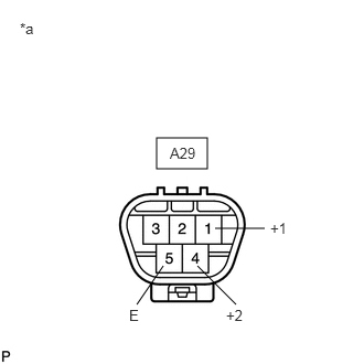
1.479,1.302 1.958,1.594 0.479,0.292 2.031,2.156 2.5,2.156 false 1.542,2.51 1.292,2.875 false 1.865,2.51 2.229,2.875 false 2.552,2.073 3.094,2.479 0.542,0.406 10 false +1 2.135,2.896 2.49,3.188 0.354,0.292 10 false +2 1.219,2.896 1.521,3.198 0.302,0.302 10 false E 0.188,0.188 0.542,0.667 0.354,0.479 10 false *a 1.604,1.365 2.167,1.688 0.563,0.323 10 false A29
*a Component without harness connected
(Windshield Wiper Motor Assembly)


Remove the windshield wiper motor assembly.

Click hereVehicle Exterior>WIPER / WASHER>FRONT WIPER MOTOR>REMOVAL


b.

Check low speed operation.

Connect a battery positive (+) lead to terminal A29-1 (+1) and a negative (-) lead to terminal A29-5 (E), and check that the motor operates at low speed.

OK:

Motor operates at low speed.


c.

Check high speed operation.

Connect a battery positive (+) lead to terminal A29-4 (+2) and a negative (-) lead to terminal A29-5 (E), and check that the motor operates at high speed.

OK:

Motor operates at high speed.


Result:
Proceed to
OK
NG


OK

2.CHECK HARNESS AND CONNECTOR (WINDSHIELD WIPER MOTOR ASSEMBLY - BATTERY AND BODY GROUND)

NG

REPLACE WINDSHIELD WIPER MOTOR ASSEMBLY

2.CHECK HARNESS AND CONNECTOR (WINDSHIELD WIPER MOTOR ASSEMBLY - BATTERY AND BODY GROUND)
a.
E144463C06
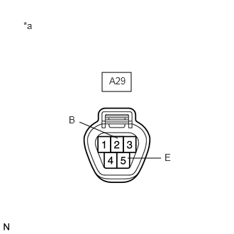
1.5,1.063 1.927,1.344 0.427,0.281 1.729,2.031 1.167,1.792 false 1.875,2.323 2.365,2.323 false 1.604,1.104 2,1.427 0.396,0.323 10 false A29 1.01,1.677 1.156,1.844 0.146,0.167 10 false B 2.417,2.229 2.698,2.396 0.281,0.167 10 false E 0.344,0.292 0.594,0.458 0.25,0.167 10 false *a
*a Front view of wire harness connector
(to Windshield Wiper Motor Assembly)


Measure the voltage according to the value(s) in the table below.

Standard Voltage:
Tester Connection Condition Specified Condition
A29-2 (B) - Body ground Ignition switch ON 11 to 14 V


b.

Measure the resistance according to the value(s) in the table below.

Standard Resistance:
Tester Connection Condition Specified Condition
A29-5 (E) - Body ground Always Below 1 Ω


Result:
Proceed to
OK
NG


OK

3.CHECK HARNESS AND CONNECTOR (WINDSHIELD WIPER MOTOR ASSEMBLY - WINDSHIELD WIPER RELAY ASSEMBLY)

NG

REPAIR OR REPLACE HARNESS OR CONNECTOR

3.CHECK HARNESS AND CONNECTOR (WINDSHIELD WIPER MOTOR ASSEMBLY - WINDSHIELD WIPER RELAY ASSEMBLY)
a.

Disconnect the I72 windshield wiper relay assembly connector and I32 windshield wiper switch assembly connector.


b.

Measure the resistance according to the value(s) in the table below.

Standard Resistance:
Tester Connection Condition Specified Condition
A29-1 (+1) - I32-2 (+1) Always Below 1 Ω
A29-1 (+1) - Body ground Always 10 kΩ or higher
A29-4 (+2) - I72-11 (+2) Always Below 1 Ω
A29-4 (+2) - I32-1 (+2) Always Below 1 Ω
A29-4 (+2) - Body ground Always 10 kΩ or higher
A29-3 (+S) - I72-1 (+SM) Always Below 1 Ω
A29-3 (+S) - Body ground Always 10 kΩ or higher


Result:
Proceed to
OK
NG


OK

PROCEED TO NEXT SUSPECTED AREA SHOWN IN PROBLEM SYMPTOMS TABLE

NG

REPAIR OR REPLACE HARNESS OR CONNECTOR