RM19V0EQ
_56
Audio / Visual / Telematics
_014601
PARK ASSIST / MONITORING
_0076583
TOYOTA PARKING ASSIST-SENSOR SYSTEM(for 2 Sensor Type)
J
PARK ASSIST / MONITORING TOYOTA PARKING ASSIST-SENSOR SYSTEM(for 2 Sensor Type) Clearance Warning Buzzer Circuit
DESCRIPTION
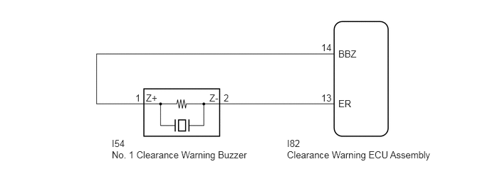
This circuit consists of the No. 1 clearance warning buzzer and clearance warning ECU assembly. An ECU-excited type buzzer is used. The ECU operates the buzzer using a sound pattern that changes depending on the distance to the obstacle.
WIRING DIAGRAM
1.979,1.354 2.104,1.583
0.125,0.229
10
1
3.271,1.354 3.448,1.583
0.177,0.229
10
2
1.635,2.021 1.969,2.25
0.333,0.229
10
I54
1.635,2.188 3.74,2.542
2.104,0.354
10
No. 1 Clearance Warning Buzzer
4.198,2.021 4.51,2.25
0.313,0.229
10
I82
4.198,2.188 6.458,2.5
2.26,0.313
10
Clearance Warning ECU Assembly
4.698,0.615 4.875,0.771
0.177,0.156
10
14
4.948,0.708 5.479,1.01
0.531,0.302
10
BBZ
4.698,1.354 4.875,1.51
0.177,0.156
10
13
4.948,1.438 5.229,1.677
0.281,0.24
10
ER
2.135,1.354 2.385,1.615
0.25,0.26
10
Z+
3.063,1.354 3.24,1.573
0.177,0.219
10
Z-
PROCEDURE
1.CHECK HARNESS AND CONNECTOR (CLEARANCE WARNING ECU ASSEMBLY - NO. 1 CLEARANCE WARNING BUZZER)
a.
Disconnect the I54 No. 1 clearance warning buzzer connector.
b.
Disconnect the I82 clearance warning ECU assembly connector.
c.
Measure the resistance according to the value(s) in the table below.
- Standard Resistance:
Tester Connection Condition Specified Condition I82-14 (BBZ) - I54-1 (Z+) Always Below 1 Ω I82-13 (ER) - I54-2 (Z-) Always Below 1 Ω I82-14 (BBZ) - Body ground Always 10 kΩ or higher I82-13 (ER) - Body ground Always 10 kΩ or higher
- Result:
Proceed to OK NG
OK
PROCEED TO NEXT SUSPECTED AREA SHOWN IN PROBLEM SYMPTOMS TABLE
NG
REPAIR OR REPLACE HARNESS OR CONNECTOR