RM19V0EQ
_51
Engine / Hybrid System
_014581
CRUISE CONTROL
_0163371
DYNAMIC RADAR CRUISE CONTROL SYSTEM
U
CRUISE CONTROL DYNAMIC RADAR CRUISE CONTROL SYSTEM TERMINALS OF ECU
CHECK DRIVING SUPPORT ECU ASSEMBLY

3.458,0.208 3.823,0.448
0.365,0.24
3.531,0.26 3.927,0.51
0.396,0.25
10
false
I191
| Terminal No. (Symbol) | Wiring Color | Terminal Description | Condition | Specified Condition |
|---|---|---|---|---|
| I191-6 (SPSW) - I191-25 (GND) | R - W-B | Steering pad switch signal
(distance control signal) |
Engine switch on (IG),
Distance control switch off |
10 to 14 V |
| I191-6 (SPSW) - I191-25 (GND) | R - W-B | Steering pad switch signal
(distance control signal) |
Engine switch on (IG),
Distance control switch on |
6 to 7 V |
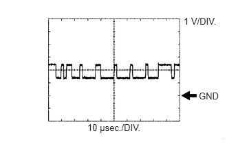
| I191-17 (CA2L) - I191-25 (GND) | LG - W-B | CAN communication signal | Engine switch on (IG) | Pulse generation
(See waveform 1) |
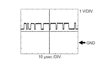
| I191-18 (CA1N) - I191-25 (GND) | W - W-B | CAN communication signal | Engine switch on (IG) | Pulse generation
(See waveform 2) |
| I191-25 (GND) - Body ground | W-B - Body ground | Earth (ground circuit of driving support ECU) | Always | Below 1 Ω |
| I191-30 (B) - I191-25 (GND) | V - W-B | Power source | Engine switch on (IG) | 11 to 14 V |
| I191-32 (WIP2) - I191-25 (GND) | V - W-B | Wiper switch signal | Engine switch on (IG),
Wiper switch off |
Below 1 V |
| I191-32 (WIP2) - I191-25 (GND) | V - W-B | Wiper switch signal | Engine switch on (IG),
Wiper switch LO position |
6 to 7 V |
| I191-32 (WIP2) - I191-25 (GND) | V - W-B | Wiper switch signal | Engine switch on (IG),
Wiper switch HI position |
11 to 14 V |
| I191-39 (CA2H) - I191-25 (GND) | L - W-B | CAN communication signal | Engine switch on (IG) | Pulse generation
(See waveform 2) |
| I191-40 (CA1P) - I191-25 (GND) | LG - W-B | CAN communication signal | Engine switch on (IG) | Pulse generation
(See waveform 1) |
a.
1.323,1.854 2.313,2.146
0.99,0.292
10
false
10 μsec./DIV.
3.01,1.375 3.354,1.573
0.344,0.198
10
false
GND
2.781,0.24 3.427,0.563
0.646,0.323
10
false
1 V/DIV.
WAVEFORM 1
i.
CAN communication signal
| Terminal Name | Between I191-17 (CA2L) and I191-25 (GND)
Between I191-40 (CA1P) and I191-25 (GND) |
| Tester Range | 1 V/DIV., 10 μsec./DIV. |
| Condition | Engine switch on (IG) |
- HINT:
-
The waveform varies depending on the CAN communication signal.
b.
1.333,1.885 2.354,2.156
1.021,0.271
10
false
10 μsec./DIV.
2.75,0.302 3.365,0.521
0.615,0.219
10
false
1 V/DIV.
3,1.406 3.406,1.604
0.406,0.198
10
false
GND
WAVEFORM 2
i.
CAN communication signal
| Terminal Name | Between I191-18 (CA1N) and I191-25 (GND)
Between I191-39 (CA2H) and I191-25 (GND) |
| Tester Range | 1 V/DIV., 10 μsec./DIV. |
| Condition | Engine switch on (IG) |
- HINT:
-
The waveform varies depending on the CAN communication signal.
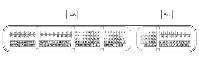
CHECK ECM
2.396,0.365 2.802,0.688
0.406,0.323
5.813,0.365 6.219,0.688
0.406,0.323
2.51,0.438 2.781,0.594
0.271,0.156
10
false
E26
5.896,0.427 6.198,0.583
0.302,0.156
10
false
A25
| Terminal No. (Symbols) | Wiring Color | Terminal Description | Condition | Specified Condition |
|---|---|---|---|---|
| A25-23 (TC) - E26-16 (E1) | P - BR | Connected to terminal TC of DLC3 | Engine switch on (IG) | 11 to 14 V |
| A25-23 (TC) - E26-16 (E1) | P - BR | Connected to terminal TC of DLC3 | Terminals TC and CG of DLC3 connected | Below 1 V |
| A25-11 (STP) - E26-16 (E1) | BE - BR | Stop light switch signal | Engine switch on (IG), Brake pedal depressed | 11 to 14 V |
| A25-11 (STP) - E26-16 (E1) | BE - BR | Stop light switch signal | Engine switch on (IG), Brake pedal released | Below 1 V |
| A25-40 (CCS) - E26-16 (E1) | W - BR | Cruise control main switch circuit | Cruise control main switch OFF | 10 kΩ or higher |
| A25-40 (CCS) - E26-16 (E1) | W - BR | Cruise control main switch circuit | Cruise control main switch ON | Below 1.5 Ω |
| A25-40 (CCS) - E26-16 (E1) | W - BR | Cruise control main switch circuit | +/RES switch ON | 235 to 245 Ω |
| A25-40 (CCS) - E26-16 (E1) | W - BR | Cruise control main switch circuit | -/SET switch ON | 617 to 643 Ω |
| A25-40 (CCS) - E26-16 (E1) | W - BR | cruise control main switch circuit | CANCEL switch ON | 1509 to 1571 Ω |
| A25-24 (ST1-) - E26-16 (E1) | GR - BR | Stop light switch signal | Engine switch on (IG), Brake pedal depressed | Below 1 V |
| A25-24 (ST1-) - E26-16 (E1) | GR - BR | Stop light switch signal | Engine switch on (IG),
Brake pedal released |
11 to 14 V |
| A25-27 (S) - E26-16 (E1) | G - BR | S shift position switch signal | Engine switch on (IG), Shift lever in S | 11 to 14 V |
| A25-27 (S) - E26-16 (E1) | G - BR | S shift position switch signal | Engine switch on (IG), Shift lever not in S | Below 1 V |
| E26-67 (D) - E26-16 (E1) | G - BR | D shift position signal | Engine switch on (IG),
Shift lever in D or S |
11 to 14 V |
| E26-67 (D) - E26-16 (E1) | G - BR | D shift position signal | Engine switch on (IG),
Shift lever in other than D or S |
Below 1 V |
| A25-43 (SFTD) - E26-16 (E1) | V - BR | Down shift switch signal | Engine switch on (IG) and shift lever in S | 11 to 14 V |
| Engine switch on (IG) and shift lever in "-" position (Down shift) | Below 1 V | |||
| A25-42 (SFTU) - E26-16 (E1) | R - BR | Up shift switch signal | Engine switch on (IG) and shift lever in S | 11 to 14 V |
| Engine switch on (IG) and shift lever in "+" position (Up shift) | Below 1 V | |||
| A25-38 (CCHG) - E26-16 (E1) | GR - BR | Cruise control main switch signal | Engine switch on (IG)
MODE switch off |
10 to 14 V |
| A25-38 (CCHG) - E26-16 (E1) | GR - BR | Cruise control main switch signal | Engine switch on (IG)
MODE switch on |
Below 1 V |
If the value is not within the specified range, the ECM may have a malfunction.