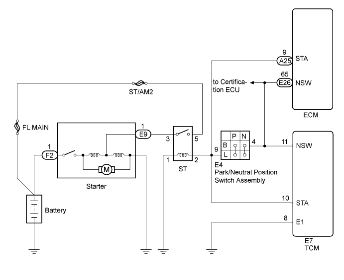
DTC P0617 Starter Relay Circuit High |
| DTC No. | DTC Detection Condition | Trouble Area |
| P0617 | When conditions (a), (b) and (c) are met, positive (+B) battery voltage 10.5 V or more applied to TCM for 20 seconds (1 trip detection logic): (a) Vehicle speed more than 20 km/h (12.43 mph) (b) Engine speed more than 1000 rpm (c) STA signal ON |
|
| 1.READ VALUE USING INTELLIGENT TESTER (STARTER SIGNAL) |
Connect the intelligent tester to the DLC3.
Turn the engine switch on (IG).
Turn the intelligent tester on.
Enter the following menus: Powertrain / ECT / Data List.
| Tester Display | Measurement Item/Range | Normal Condition | Diagnostic Note |
| Starter Signal | Starter signal/ Open or Close | Open: Starter operating Close: Starter not operating | - |
Crank the engine.
Read the value displayed on the intelligent tester.
| Tester Display | Condition | Specified Condition |
| Starter Signal | Engine switch on (IG) | Close |
| Starter Signal | Engine is cranking | Open |
|
| ||||
| OK | ||
 | ||
| ||
| 2.INSPECT PARK/NEUTRAL POSITION SWITCH ASSEMBLY |
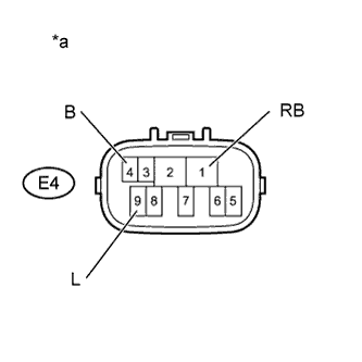 |
Disconnect the park/neutral position switch assembly connector.
Measure the resistance according to the value(s) in the table below when the shift lever is moved to each position.
| Tester Connection | Condition | Specified Condition |
| E4-4 (B) - E4-9 (L) | P | Below 1 Ω |
| N | Below 1 Ω | |
| Except P and N | 10 kΩ or higher | |
| E4-1 (RB) - E4-9 (L) | P | 10 kΩ or higher |
| R | 10 kΩ or higher | |
| N | 10 kΩ or higher | |
| D | 10 kΩ or higher |
| *a | Component without harness connected (Park/Neutral Position Switch Assembly) |
|
| ||||
| OK | |
 |
| 3.CHECK HARNESS AND CONNECTOR (TCM - PARK/NEUTRAL POSITION SWITCH ASSEMBLY) |
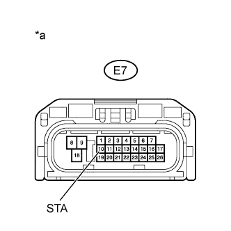 |
Disconnect the TCM connector.
Remove the ST relay from the engine room relay block and junction block assembly.
Disconnect the park/neutral position switch assembly connector.
Measure the voltage according to the value(s) in the table below.
| Tester Connection | Condition | Specified Condition |
| E7-10 (STA) - Body ground | Engine switch on (IG) | Below 1 V |
| *a | Front view of wire harness connector (to TCM) |
|
| ||||
| OK | |
|
| 4.CHECK WHETHER DTC OUTPUT RECURS |
Connect the intelligent tester to the DLC3.
Turn the engine switch on (IG).
Turn the intelligent tester on.
Clear the DTCs (Click here).
Drive the vehicle in accordance with the driving pattern described in the Confirmation Driving Pattern.
Enter the following menus: Powertrain / ECT/ DTC.
Read the DTCs.
| Result | Proceed to |
| DTC is not output | OK |
| DTC P0617 is output | NG |
|
| ||||
| OK | ||
| ||
| ||

