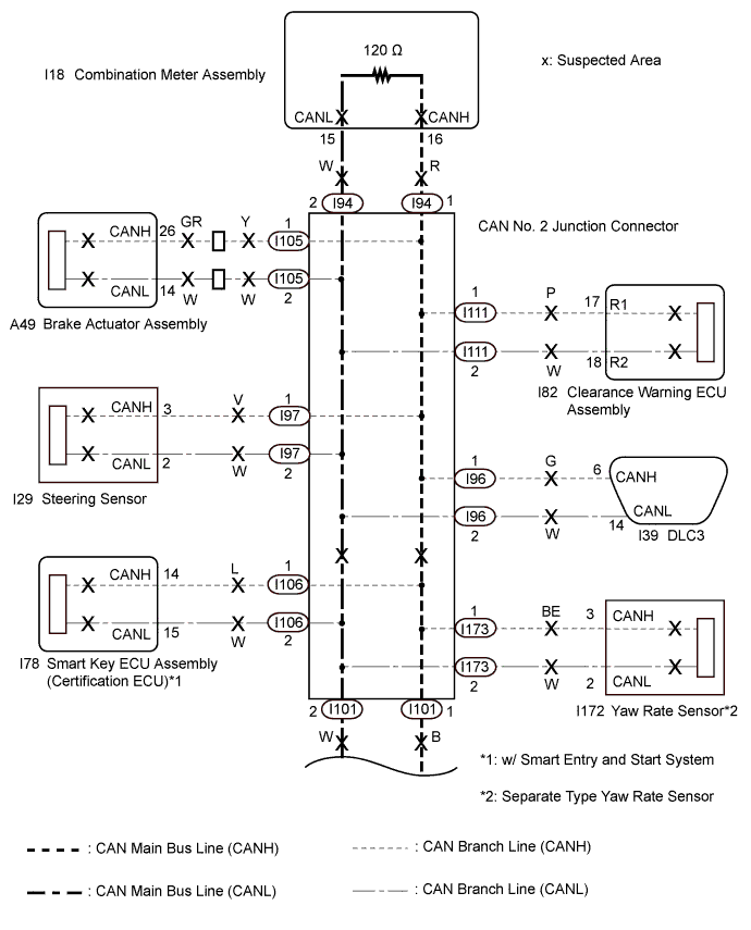
CAN COMMUNICATION SYSTEM > Check CAN Bus Line for Short to +B (RHD Models) |
| Symptom | Trouble Area |
| No resistance exists between terminals 6 (CANH) and 16 (BAT) or 14 (CANL) and 16 (BAT) of DLC3. |
|
| 1.CHECK FOR SHORT TO +B IN CAN BUS LINE (DLC3 BRANCH LINE) |
Disconnect the cable from the negative (-) battery terminal.
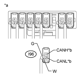 |
Disconnect the DLC3 branch line connector (I96) from the CAN No. 2 junction connector.
| *a | Rear view of wire harness connector (to CAN No. 2 Junction Connector) |
| *b | to DLC3 |
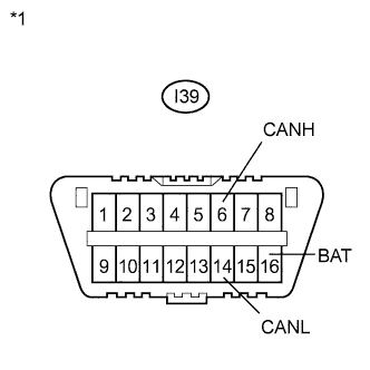 |
Measure the resistance according to the value(s) in the table below.
| Tester Connection | Condition | Specified Condition |
| I39-6 (CANH) - I39-16 (BAT) | Cable disconnected from negative (-) battery terminal | 6 kΩ or higher |
| I39-14 (CANL) - I39-16 (BAT) | Cable disconnected from negative (-) battery terminal | 6 kΩ or higher |
| *1 | DLC3 |
|
| ||||
| OK | |
 |
| 2.CHECK FOR SHORT TO +B IN CAN BUS LINE |
Reconnect the DLC3 branch line connector (I96) to the CAN No. 2 junction connector.
|
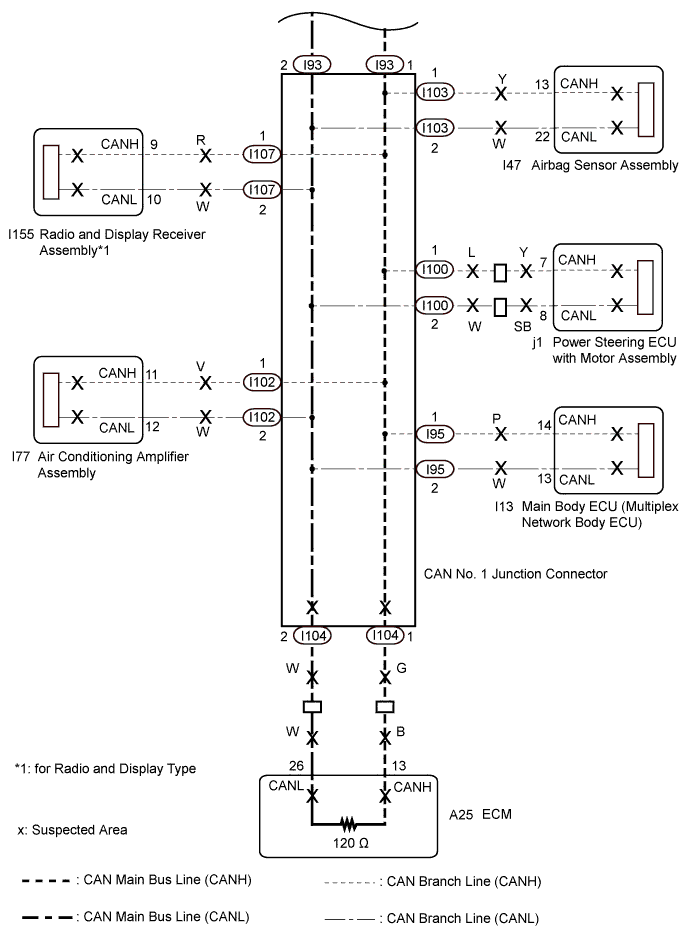
Disconnect the connectors from the CAN No. 1 junction connector and CAN No. 2 junction connector one at a time.
| *1 | DLC3 |
Using an ohmmeter, measure the resistance between terminals 6 (CANH) and 16 (BAT), and between terminals 14 (CANL) and 16 (BAT) of the DLC3 each time a connector is disconnected.
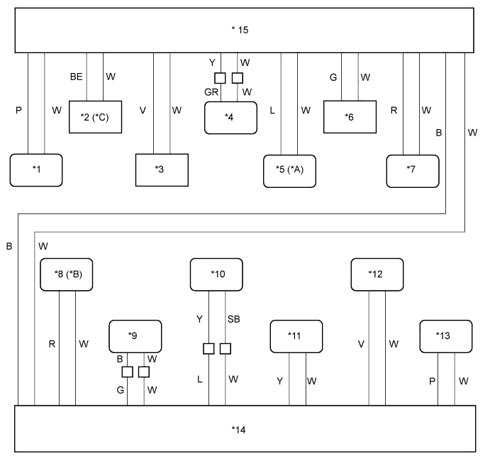
| *A | w/ Smart Entry and Start System | *B | for Radio and Display Type |
| *C | Separate Type Yaw Rate Sensor | - | - |
| *1 | Clearance Warning ECU Assembly | *2 | Yaw Rate Sensor |
| *3 | Steering Sensor | *4 | Brake Actuator Assembly |
| *5 | Smart Key ECU Assembly (Certification ECU) | *6 | DLC3 |
| *7 | Combination Meter Assembly | *8 | Radio and Display Receiver Assembly |
| *9 | ECM | *10 | Power Steering ECU with Motor Assembly |
| *11 | Airbag Sensor Assembly | *12 | Air Conditioning Amplifier Assembly |
| *13 | Main Body ECU (Multiplex Network Body ECU) | *14 | CAN No. 1 Junction Connector |
| *15 | CAN No. 2 Junction Connector | - | - |
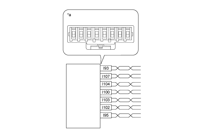
| *a | Component without harness connected (CAN No. 1 Junction Connector) | - | - |
| CAN No. 1 Junction Connector Side | Code | Color (CANH Side) | Color (CANL Side) |
| Main body ECU (Multiplex network body ECU) | I95 | P | W |
| Air conditioning amplifier assembly | I102 | V | W |
| Airbag sensor assembly | I103 | Y | W |
| Power steering ECU with motor assembly | I100 | L | W |
| ECM | I104 | G | W |
| Radio and display receiver assembly*1 | I107 | R | W |
| CAN main bus line (bus line connecting CAN No. 1 junction connector and CAN No. 2 junction connector) | I93 | B | W |
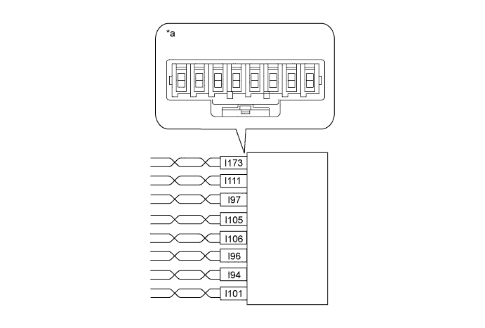
| *a | Component without harness connected (CAN No. 2 Junction Connector) | - | - |
| CAN No. 2 Junction Connector Side | Code | Color (CANH Side) | Color (CANL Side) |
| CAN main bus line (bus line connecting CAN No. 1 junction connector and CAN No. 2 junction connector) | I101 | B | W |
| Combination meter assembly | I94 | R | W |
| DLC3 | I96 | G | W |
| Smart key ECU assembly (Certification ECU)*1 | I106 | L | W |
| Brake actuator assembly | I105 | Y | W |
| Steering sensor | I97 | V | W |
| Yaw rate sensor*2 | I173 | BE | W |
| Clearance warning ECU assembly | I111 | P | W |
| Symptom | Proceed to |
| The resistance between terminals 6 (CANH) and 16 (BAT), or the resistance between 14 (CANL) and 16 (BAT) is still below 6 kΩ when all the specified connectors are disconnected from the CAN junction connector. (There is a short to +B in the CAN main bus lines between the CAN No. 1 junction connector and CAN No. 2 junction connector.) | A |
| The resistance between terminals 6 (CANH) and 16 (BAT), or the resistance between 14 (CANL) and 16 (BAT) becomes normal (6 kΩ or more) when a connector is disconnected from the CAN junction connector. (There is a short to +B in one of the areas that relate to one or more of the disconnected bus lines.) | B |
When there is a short to +B in one or more of the bus lines that connect to an ECU (or sensor):
Reconnect all of the connectors to the CAN junction connector, except for the one that was disconnected last (the bus line that is shorted to +B). Check that the resistance shown on the tester is normal (6 kΩ or more) to confirm that there is a short to +B in the one bus line only.
When there is no short to +B in any of the bus lines that connect to the ECUs and sensors:
With all the specified connectors for ECUs and sensors disconnected, proceed with the inspection of the CAN bus main lines between the CAN No. 1 junction connector and CAN No. 2 junction connector.
|
| ||||
| A | |
|
| 3.CHECK CAN NO. 2 JUNCTION CONNECTOR |
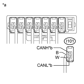 |
Disconnect the CAN main bus line connector (I101) from the CAN No. 2 junction connector.
| *a | Rear view of wire harness connector (to CAN No. 2 Junction Connector) |
| *b | to CAN No. 1 Junction Connector |
|
Measure the resistance according to the value(s) in the table below.
| Tester Connection | Condition | Specified Condition |
| I39-6 (CANH) - I39-16 (BAT) | Cable disconnected from negative (-) battery terminal | 6 kΩ or higher |
| I39-14 (CANL) - I39-16 (BAT) | Cable disconnected from negative (-) battery terminal | 6 kΩ or higher |
| *1 | DLC3 |
|
| ||||
| OK | |
|
| 4.CHECK CAN NO. 1 JUNCTION CONNECTOR |
Reconnect the CAN main bus line connector (I101) to the CAN No. 2 junction connector.
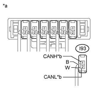 |
Disconnect the CAN main bus line connector (I93) from the CAN No. 1 junction connector.
| *a | Rear view of wire harness connector (to CAN No. 1 Junction Connector) |
| *b | to CAN No. 2 Junction Connector |
|
Measure the resistance according to the value(s) in the table below.
| Tester Connection | Condition | Specified Condition |
| I39-6 (CANH) - I39-16 (BAT) | Cable disconnected from negative (-) battery terminal | 6 kΩ or higher |
| I39-14 (CANL) - I39-16 (BAT) | Cable disconnected from negative (-) battery terminal | 6 kΩ or higher |
| *1 | DLC3 |
|
| ||||
| OK | ||
 | ||
| ||
| 5.CHECK FOR SHORT TO +B IN CAN BUS LINE (ECU, SENSOR) |
Reconnect the connector of the bus line that is shorted to +B to the CAN junction connector (the connector that caused the bus line resistance to change to 6 kΩ or more when it was disconnected).
|
Disconnect the connector that includes the DLC3 connected CAN lines (such as CANH and CANL) from the ECU (or sensor) to which the bus line shorted to +B is connected (Click here).
Measure the resistance according to the value(s) in the table below.
| Tester Connection | Condition | Specified Condition |
| I39-6 (CANH) - I39-16 (BAT) | Cable disconnected from negative (-) battery terminal | 6 kΩ or higher |
| I39-14 (CANL) - I39-16 (BAT) | Cable disconnected from negative (-) battery terminal | 6 kΩ or higher |
| *1 | DLC3 |
|
| ||||
| OK | ||
| ||
| ||

