
REAR SUNSHADE SYSTEM > TERMINALS OF ECU |
| CHECK REAR SUNSHADE RELAY (REAR WINDOW SHADE ASSEMBLY) |
Disconnect the N19 rear sunshade relay (rear window shade assembly) connector.
Measure the voltage and resistance according to the value(s) in the table below.
| Tester Connection | Wiring Color | Terminal Description | Condition | Specified Condition |
| N19-7 (IG) - N19-1 (E) | V - W-B | IG power supply | Engine switch off | Below 1 V |
| N19-7 (IG) - N19-1 (E) | V - W-B | IG power supply | Engine switch on (IG) | 11 to 14 V |
| N19-8 (B) - N19-1 (E) | P - W-B | Battery power supply | Engine switch off | 11 to 14 V |
| N19-1 (E) - Body ground | W-B - Body ground | Ground | Always | Below 1 Ω |
Reconnect the N19 rear sunshade relay (rear window shade assembly) connector.
Measure the voltage according to the value(s) in the table below.
| Tester Connection | Wiring Color | Terminal Description | Condition | Specified Condition |
| N19-3 (REV) - N19-1 (E) | B - W-B | Reverse signal | Engine switch on (IG), shift lever in any position other than R | 11 to 14 V |
| N19-3 (REV) - N19-1 (E) | B - W-B | Reverse signal | Engine switch on (IG), shift lever in R | Below 1 V |
| N19-5 (SW) - N19-1 (E) | R - W-B | Rear sunshade switch signal | Engine switch on (IG), rear sunshade switch not pushed | 11 to 14 V |
| N19-5 (SW) - N19-1 (E) | R - W-B | Rear sunshade switch signal | Engine switch on (IG), rear sunshade switch pushed | Below 1.5 V |
| N19-4 (RSW) - N19-1 (E) | L - W-B | Rear sunshade switch (cooler control switch assembly) signal | Engine switch on (IG), rear sunshade switch (cooler control switch assembly) not pushed | 11 to 14 V |
| N19-4 (RSW) - N19-1 (E) | L - W-B | Rear sunshade switch (cooler control switch assembly) signal | Engine switch on (IG), rear sunshade switch (cooler control switch assembly) pushed | Below 1.5 V |
| CHECK INSTRUMENT PANEL JUNCTION BLOCK ASSEMBLY AND MAIN BODY ECU (MULTIPLEX NETWORK BODY ECU) |
Disconnect the I12 and MB junction block connectors.
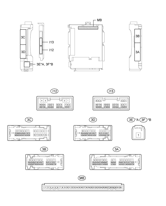
| *A | for LHD | *B | for RHD |
Measure the voltage and resistance according to the value(s) in the table below.
| Tester Connection | Wiring Color | Terminal Description | Condition | Specified Condition |
| MB-11 (GND1) - Body ground | - | Ground | Always | Below 1 Ω |
| I12-3 (GND2) - Body ground | W-B - Body ground | Ground | Always | Below 1 Ω |
| MB-30 (BECU) - Body ground | - | Battery power supply | Always | 11 to 14 V |
| MB-29 (ACC) - Body ground | - | ACC power supply | Engine switch on (ACC) | 11 to 14 V |
| MB-29 (ACC) - Body ground | - | ACC power supply | Engine switch off | Below 1 V |
| MB-31 (ALTB) - Body ground | - | Battery power supply | Always | 11 to 14 V |
| MB-32 (IG) - Body ground | - | IG power supply | Engine switch on (IG) | 11 to 14 V |
| MB-32 (IG) - Body ground | - | IG power supply | Engine switch off | Below 1 V |
Reconnect the I12 and MB junction block connectors.
Measure the voltage according to the value(s) in the table below.
| Tester Connection | Wiring Color | Terminal Description | Condition | Specified Condition |
| I13-15 (REV) - Body ground | B - Body ground | Reverse signal | Engine switch on (IG), shift lever in any position other than R | 11 to 14 V |
| I13-15 (REV) - Body ground | B - Body ground | Reverse signal | Engine switch on (IG), shift lever in R | Below 1 V |