CYLINDER HEAD > INSPECTION |
| 1. INSPECT CYLINDER HEAD FOR WARPAGE |
![]() |
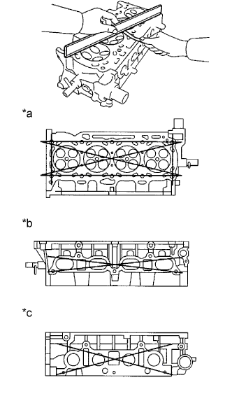
Using a precision straight edge and a feeler gauge, measure the surface contacting the cylinder block and the manifolds for warpage.
| Item | Specified Condition |
| Cylinder block side | 0.08 mm (0.00315 in.) |
| Intake manifold side | 0.08 mm (0.00315 in.) |
| Exhaust manifold side | 0.08 mm (0.00315 in.) |
| *a | Cylinder Block Side |
| *b | Intake Manifold Side |
| *c | Exhaust Manifold Side |
| 2. INSPECT CYLINDER HEAD FOR CRACKS |
![]() |
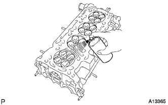
Using a dye penetrant, check the intake ports, exhaust ports and cylinder surface for cracks.
If cracked, replace the cylinder head.
| 3. INSPECT CAMSHAFT THRUST CLEARANCE |
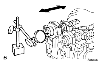
Install the camshafts .
![]() |
Using a dial indicator, measure the thrust clearance while moving the camshaft back and forth.
| Item | Specified Condition |
| Intake | 0.040 to 0.095 mm (0.00157 to 0.00374 in.) |
| Exhaust | 0.080 to 0.135 mm (0.00315 to 0.00532 in.) |
| Item | Specified Condition |
| Intake | 0.110 mm (0.00433 in.) |
| Exhaust | 0.150 mm (0.00591 in.) |
| 4. INSPECT CAMSHAFT OIL CLEARANCE |
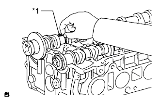
Clean the bearing caps and camshaft journals.
Place the camshafts on the cylinder head.
![]() |
Lay a strip of Plastigage across each of the camshaft journals.
| *1 | Plastigage |
Install the bearing caps .
Remove the bearing caps .
![]() |
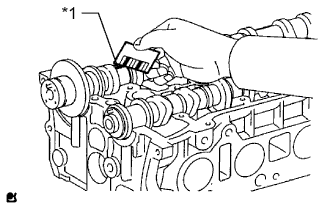
Measure the Plastigage at its widest point.
| Item | Specified Condition |
| Intake No. 1 journal | 0.007 to 0.038 mm (0.000276 to 0.00150 in.) |
| Exhaust No. 1 journal | 0.040 to 0.079 mm (0.00157 to 0.00311 in.) |
| Other journals | 0.025 to 0.062 mm (0.000984 to 0.00244 in.) |
| Item | Specified Condition |
| Intake No. 1 journal | 0.070 mm (0.00276 in.) |
| Other journals | 0.100 mm (0.00394 in.) |
| *1 | Plastigage |
![]() |
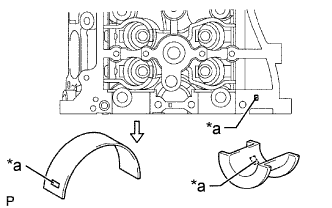
Check the number mark shown in the illustration.
| Mark 1 | Mark 2 | Mark 3 |
| 40.000 to 40.009 mm (1.5748 to 1.5752 in.) | 40.010 to 40.017 mm (1.5752 to 1.5755 in.) | 40.018 to 40.025 mm (1.5755 to 1.5758 in.) |
| Mark 1 | Mark 2 | Mark 3 |
| 2.000 to 2.004 mm (0.0787 to 0.0789 in.) | 2.005 to 2.008 mm (0.0789 to 0.0791 in.) | 2.009 to 2.012 mm (0.0791 to 0.0792 in.) |
| *a | Number Mark |
| 5. INSPECT INNER COMPRESSION SPRING |
![]() |
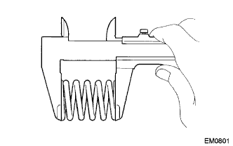
Using a vernier caliper, measure the free length of the inner compression spring.
![]() |
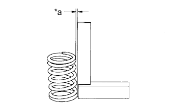
Using a steel set square, measure the deviation of the inner compression spring.
| *a | Deviation |
| 6. INSPECT INTAKE VALVE |
![]() |
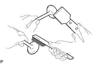
Using a gasket scraper, scrape off any carbon on the valve head.
Using a wire brush, thoroughly clean the intake valve.
![]() |
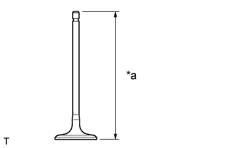
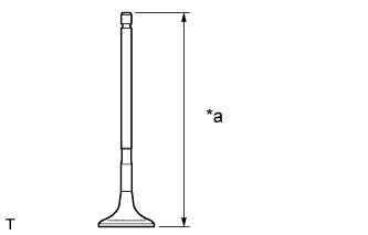
Using a vernier caliper, measure the overall length of the intake valve.
| *a | Overall Length |
![]() |
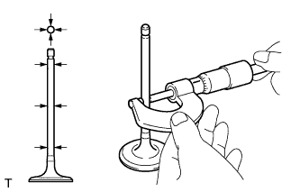
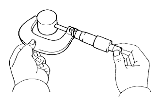
Using a micrometer, measure the diameter of the valve stem.
![]() |
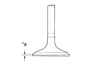
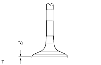
Using a vernier caliper, measure the valve head margin thickness.
| *a | Margin Thickness |
| 7. INSPECT EXHAUST VALVE |
![]() |
Using a gasket scraper, scrape off any carbon on the valve head.
Using a wire brush, thoroughly clean the exhaust valve.
![]() |
Using a vernier caliper, measure the overall length of the exhaust valve.
| *a | Overall Length |
![]() |
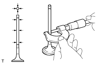
Using a micrometer, measure the diameter of the valve stem.
![]() |
Using a vernier caliper, measure the valve head margin thickness.
| *a | Margin Thickness |
| 8. INSPECT INTAKE VALVE GUIDE BUSH |
![]() |
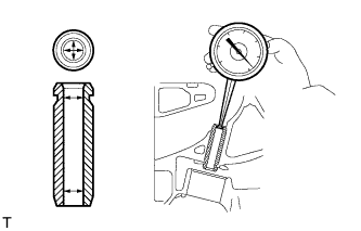
Using a caliper gauge, measure the inside diameter of the intake valve guide bush.
Subtract the valve stem diameter measurement from the intake valve guide bush inside diameter measurement.
| 9. INSPECT EXHAUST VALVE GUIDE BUSH |
![]() |
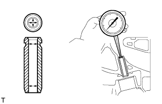
Using a caliper gauge, measure the inside diameter of the exhaust valve guide bush.
Subtract the valve stem diameter measurement from the guide bushing inside diameter measurement.
| 10. INSPECT VALVE LIFTER |
![]() |
Using a micrometer, measure the lifter diameter.
![]() |
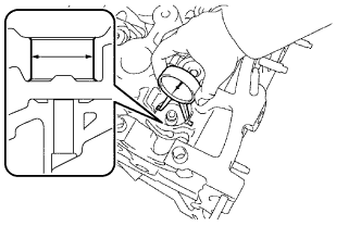
Using a caliper gauge, measure the lifter bore diameter of the cylinder head.
Subtract the lifter diameter measurement from the lifter bore diameter measurement.
| 11. INSPECT CYLINDER HEAD SET BOLT |
![]() |
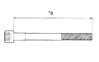
Using a vernier caliper, measure the length of the cylinder head set bolts from the seat to the end.
| *a | Measurement Length |