 |
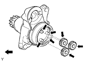
Apply grease to the planetary gears and pin parts of the planetary shaft.
 | High-temperature grease |
STARTER (for 1.7 kW Type) > REASSEMBLY |
| 1. INSTALL PLANETARY GEAR |
|
Apply grease to the planetary gears and pin parts of the planetary shaft.
| High-temperature grease |
Install the 3 planetary gears.
| 2. INSTALL STARTER ARMATURE ASSEMBLY |
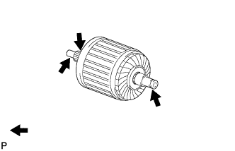 |
Apply grease to the armature shaft.
| High-temperature grease |
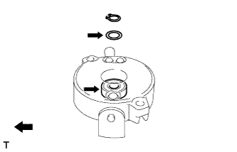 |
Apply high-temperature grease to the plate washer and bearing as shown in the illustration.
| High-temperature grease |
Install the starter armature assembly to the starter commutator end frame assembly.
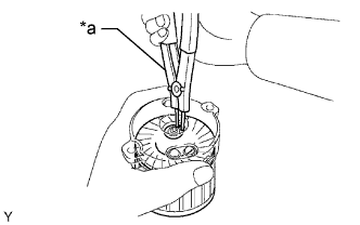 |
Using snap ring pliers, install the plate washer and a new snap ring.
| *a | Snap Ring Pliers |
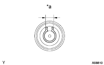 |
Using a vernier caliper, measure the length of the snap ring.
| *a | Length |
| 3. INSTALL STARTER COMMUTATOR END FRAME COVER |
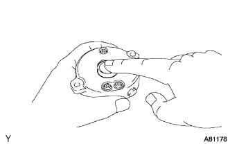 |
Install the end frame cover to the starter commutator end frame assembly.
| 4. INSTALL STARTER ARMATURE PLATE |
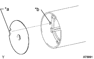 |
Insert the starter armature plate to the starter yoke assembly.
| *a | Keyway |
| *b | Key |
Align the keyway of the starter armature plate with the key inside the starter yoke assembly, and install the starter armature plate.
| 5. INSTALL STARTER COMMUTATOR END FRAME ASSEMBLY |
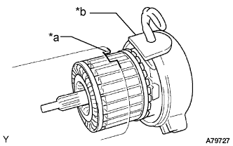 |
Align the rubber of the starter commutator end frame assembly with the cutout of the starter yoke assembly.
| *a | Cutout |
| *b | Rubber |
Install the starter commutator end frame assembly to the starter yoke assembly.
| 6. INSTALL STARTER YOKE ASSEMBLY |
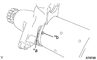 |
Align the protrusion of the starter yoke assembly with the cutout of the starter drive housing.
| *a | Cutout |
| *b | Protrusion |
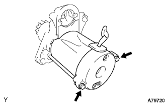 |
Install the starter yoke assembly with the 2 through-bolts.
| 7. INSTALL REPAIR SERVICE STARTER KIT |
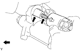 |
Apply grease to the plunger and the hook.
| High-temperature grease |
Hang the plunger hook of the magnetic switch on the drive lever.
Install the plunger and return spring.
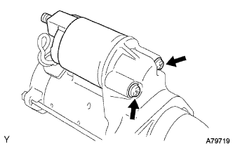 |
Install the magnetic switch with the 2 screws.
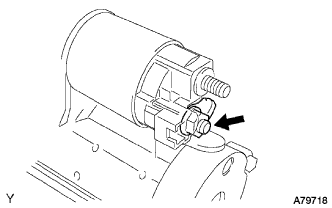 |
Connect the lead wire to the magnetic switch with the nut.