FUEL TANK > INSTALLATION |
| 1. INSTALL NO. 4 FUEL TUBE CLAMP |
Install the 3 No. 4 fuel tube clamps.
| 2. INSTALL FUEL MAIN TUBE SUPPORT |
Install the fuel main tube support with the bolt.
| 3. INSTALL FUEL PUMP TUBE SUB-ASSEMBLY |
Install the fuel pump tube sub-assembly to the fuel main tube support and No. 4 fuel tube clamp.
| 4. INSTALL FUEL CUT OFF WITH TUBE VALVE ASSEMBLY |
Install 2 new fuel tank breather tube gaskets to the fuel tank assembly.
![]() |
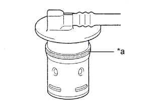
Apply a light coat of fuel around 2 new fuel cut off with tube valve assemblies as shown in the illustration, and carefully insert them into the fuel tank assembly.
| *a | Apply fuel around the valve |
Check that the fuel cut off with tube valve assembly is fully inserted.
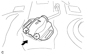
| 5. INSTALL NO. 3 FUEL TANK PROTECTOR |
![]() |
Install the No. 3 fuel tank protector by sliding it as shown in the illustration.
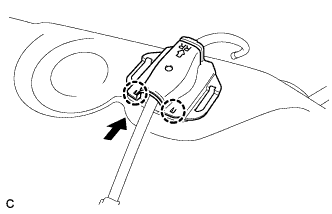
| 6. INSTALL NO. 2 FUEL TANK PROTECTOR |
![]() |
Install the No. 2 fuel tank protector by sliding it as shown in the illustration.
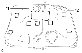
| 7. INSTALL NO. 1 FUEL TANK CUSHION |
![]() |
Install a new No. 1 fuel tank cushion as shown in the illustration.
| *1 | No. 1 Fuel Tank Cushion |
| *2 | No. 2 Fuel Tank Cushion |
| 8. INSTALL NO. 2 FUEL TANK CUSHION |
Install 7 new No. 2 fuel tank cushions as shown in the illustration.
| 9. INSTALL FUEL TANK ASSEMBLY |
Install the 4 clip nuts.
![]() |
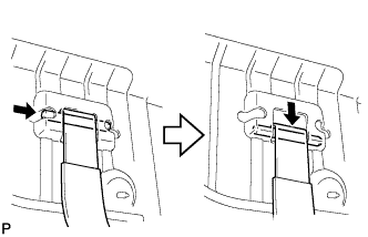
Install the 2 fuel tank bands with the 2 pins.
Support the fuel tank assembly using an engine lifter.
![]() |
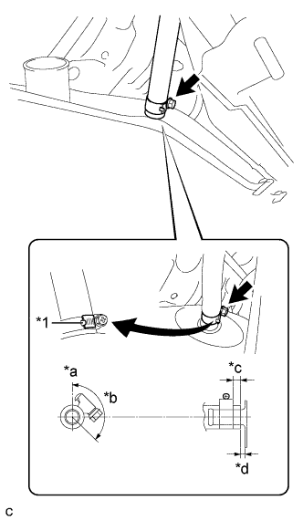
Raise the engine lifter so that the breather tube fuel hose can be connected as shown in the illustration.
| *1 | Claw |
| *a | Up |
| *b | 135° |
| *c | 2 to 7 mm (0.0787 to 0.276 in.) |
| *d | 0 to 3 mm (0 to 0.118 in.) |
![]() |
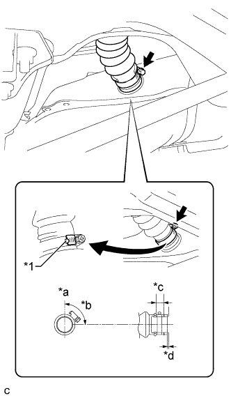
Connect the fuel tank to filler pipe hose to the fuel tank assembly as shown in the illustration, then fit the hose with the clamp.
| *1 | Claw |
| *a | Up |
| *b | 90° |
| *c | Clamp Area |
| *d | 0 to 3 mm (0 to 0.118 in.) |
Slightly raise the engine lifter, then install the fuel tank assembly to the vehicle.
Tighten the 2 bolts of the fuel tank bands.
![]() |
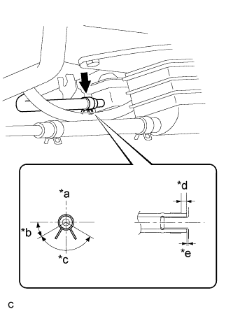
Connect the fuel emission hose to the charcoal canister, then fit it with the clip as shown in the illustration.
| *a | Up |
| *b | 30° |
| *c | 120° (Clip Area) |
| *d | 2 to 7 mm (0.0787 to 0.276 in.) |
| *e | 0 to 3 mm (0 to 0.118 in.) |
| 10. CONNECT FUEL PUMP TUBE SUB-ASSEMBLY |
![]() |
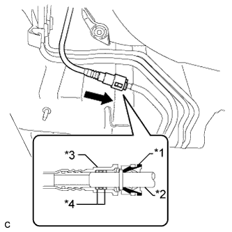
Align the fuel tube connector with the fuel pipe, then push in the fuel tube connector until the retainer makes a "click" sound.
| *1 | Retainer |
| *2 | Fuel Pipe |
| *3 | Fuel Tube Connector |
| *4 | O-ring |
| 11. INSTALL LOWER CENTER FUEL TANK PROTECTOR |
Install the lower center fuel tank protector with the 4 bolts.
| 12. INSTALL REAR NO. 1 STABILIZER BAR BRACKET |
Install the 2 rear No. 1 stabilizer bar brackets with the 4 bolts.
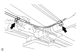
| 13. INSTALL NO. 3 PARKING BRAKE CABLE ASSEMBLY |
![]() |
Install the No. 3 parking brake cable assembly with the bolt and nut.
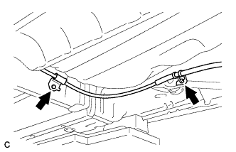
| 14. INSTALL NO. 2 PARKING BRAKE CABLE ASSEMBLY |
![]() |
Install the No. 2 parking brake cable assembly with the bolt and nut.
| 15. INSTALL NO. 1 FLOOR UNDER COVER |
Install the No. 1 floor under cover with the 5 nuts and 2 clips.
| 16. INSTALL NO. 2 FLOOR UNDER COVER |
Install the No. 2 floor under cover with the 6 nuts.
Install the 2 clips.
| 17. INSTALL CENTER EXHAUST PIPE ASSEMBLY |
| 18. INSTALL FUEL SUCTION TUBE WITH PUMP AND GAUGE ASSEMBLY |
| 19. ADD FUEL |
| 20. INSPECT FOR EXHAUST GAS LEAK |