AUTOMATIC TRANSAXLE UNIT > REASSEMBLY |
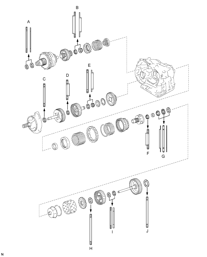
| 1. BEARING POSITION |
| Mark | Front Race Diameter Inside / Outside | Thrust Bearing Diameter Inside / Outside | Rear Race Diameter Inside / Outside |
| A | - | 53.0 mm (2.087 in.) / 78.2 mm (3.079 in.) | 52.1 mm (2.051 in.) / 75.5 mm (2.972 in.) |
| B | - | 37.73 mm (1.4854 in.) / 58.0 mm (2.283 in.) | 29.9 mm (1.177 in.) / 55.5 mm (2.185 in.) |
| C | - | 33.85 mm (1.3327 in.) / 52.2 mm (2.055 in.) | - |
| D | - | 23.5 mm (0.925 in.) / 44.0 mm (1.732 in.) | - |
| E | - | 36.3 mm (1.492 in.) / 52.2 mm (2.055 in.) | 34.5 mm (1.358 in.) / 48.5 mm (1.909 in.) |
| F | - | 34.6 mm (1.362 in.) / 52.2 mm (2.055 in.) | - |
| G | 40.3 mm (1.587 in.) / 58.0 mm (2.283 in.) | 38.6 mm (1.520 in.) / 60.0 mm (2.362 in.) | 38.6 mm (1.520 in.) / 58.0 mm (2.283 in.) |
| H | - | 53.6 mm (2.110 in.) / 69.6 mm (2.740 in.) | - |
| I | - | 33.7 mm (1.327 in.) / 48.2 mm (1.898 in.) | 30.3 mm (1.193 in.) / 46.2 mm (1.819 in.) |
| J | - | 53.6 mm (2.110 in.) / 70.18 mm (2.763 in.) or 69.6 mm (2.740 in.) | - |
| 2. INSTALL DIFFERENTIAL GEAR LUBE APPLY TUBE |
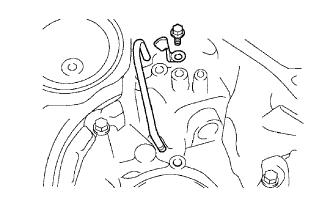 |
Install the differential gear lube apply tube and No. 2 transaxle apply tube clamp to the transaxle housing with the bolt.
| 3. INSTALL COUNTER DRIVE GEAR ANGULAR BALL BEARING |
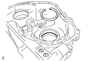 |
Install a new snap ring to the transaxle case.
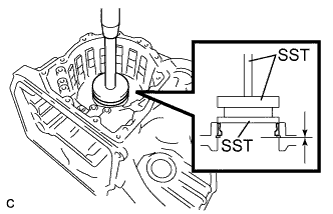 |
Using SST and a press, install a new counter drive gear angular ball bearing outer race (rear side) to the transaxle case.
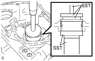 |
Using SST and a press, install a new counter drive gear angular ball bearing outer race (front side) to the transaxle case.
Install 2 new counter drive gear angular ball bearings to the transaxle case.
| 4. INSTALL COUNTER DRIVE GEAR |
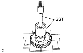 |
Using SST and a press, install a new counter drive gear angular ball bearing inner race (front side) to the counter drive gear.
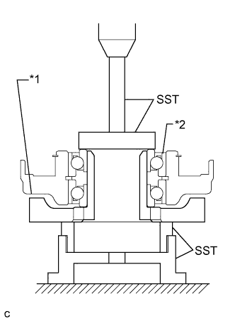 |
Using SST and a press, install the counter drive gear and a new counter drive gear angular ball bearing inner race (rear side) to the transaxle case.
| *1 | Counter Drive Gear |
| *2 | Counter Drive Gear Angular Ball Bearing |
| 5. INSTALL 1ST AND REVERSE BRAKE PISTON |
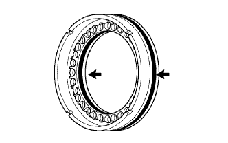 |
Coat 2 new O-rings with ATF.
Install the 2 O-rings to the 1st and reverse brake piston.
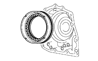 |
Coat the 1st and reverse brake piston with ATF, and install it to the transaxle case.
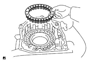 |
Install the 1st and reverse brake return spring to the 1st and reverse brake piston.
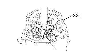 |
Using SST, a press and snap ring expander, press the 1st and reverse brake return spring and snap ring to the transaxle case.
| 6. INSTALL FRONT PLANETARY RING GEAR |
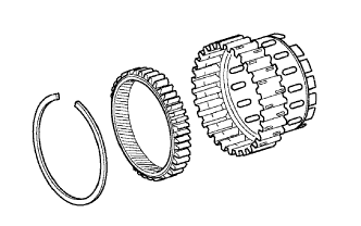 |
Using a screwdriver, install the front planetary ring gear and brake hub snap ring to the 2nd brake hub.
| 7. INSTALL FRONT PLANETARY GEAR ASSEMBLY |
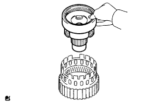 |
Install the front planetary gear assembly to the 2nd brake hub.
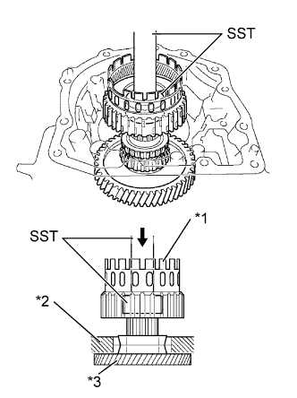 |
Using SST and a press, press-fit the front planetary gear assembly.
| *1 | 2nd Brake Hub with Front Planetary Gear Assembly |
| *2 | Transaxle Case |
| *3 | Counter Drive Gear |
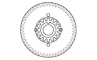 |
Install a new lock washer as shown in the illustration.
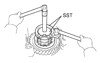 |
Using SST, install the lock nut.
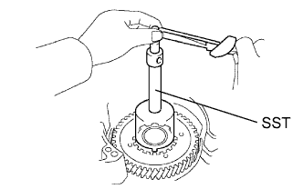 |
Using SST and a torque wrench, measure the turning torque of the bearing while rotating SST at 60 rpm. When the measured value is not within the specified value, gradually tighten the nut until it reaches the specified value.
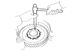 |
Using a chisel and hammer, stake the lock washer.
| 8. INSTALL INPUT SUN GEAR |
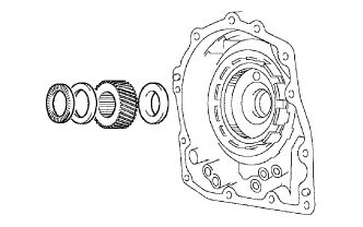 |
Install the 2 thrust bearings, bearing race and input sun gear to the front planetary gear assembly.
| Item | Inside | Outside |
| Bearing | 34.6 mm (1.362 in.) | 52.2 mm (2.055 in.) |
| Bearing Race | 40.3 mm (1.587 in.) | 58.0 mm (2.283 in.) |
| Bearing | 38.6 mm (1.520 in.) | 60.0 mm (2.362 in.) |
| 9. INSTALL REAR PLANETARY GEAR ASSEMBLY |
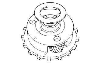 |
Install the No. 3 thrust bearing race to the rear planetary gear assembly.
| Item | Inside | Outside |
| Bearing Race | 38.6 mm (1.520 in.) | 58.0 mm (2.283 in.) |
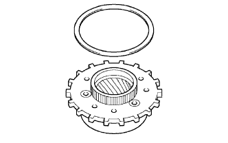 |
Install the thrust washer to the rear planetary gear assembly.
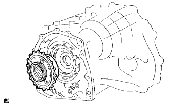 |
Install the rear planetary gear assembly to the transaxle case.
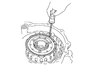 |
Using a screwdriver, install the snap ring to the 2nd brake hub.
| 10. INSTALL 1ST AND REVERSE BRAKE CLUTCH DISC |
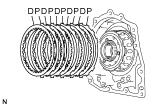 |
Install the 5 plates and 5 1st and reverse brake clutch discs.
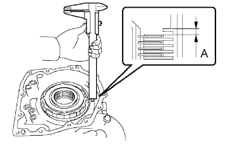 |
Using a vernier caliper, measure the distance between the 1st and reverse brake clutch disc surface and the contact surface of the 2nd brake cylinder and transaxle case (Dimension A).
Select an appropriate flange so that the piston stroke will meet the specified value.
| Mark | Thickness | Mark | Thickness |
| 1 | 1.8 mm (0.0709 in.) | 5 | 2.2 mm (0.0866 in.) |
| 2 | 1.9 mm (0.0748 in.) | 6 | 2.3 mm (0.0905 in.) |
| 3 | 2.0 mm (0.0787 in.) | 7 | 2.4 mm (0.0945 in.) |
| 4 | 2.1 mm (0.0827 in.) | 8 | 2.5 mm (0.0984 in.) |
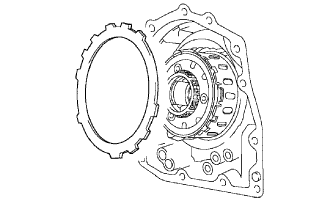 |
Install the flange.
| 11. INSTALL OUTER ONE-WAY CLUTCH SLEEVE |
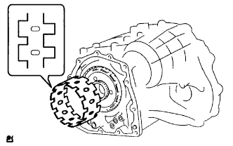 |
Install the outer one-way clutch sleeve to the transaxle case.
| 12. INSTALL ONE-WAY CLUTCH ASSEMBLY |
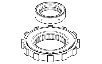 |
Install the one-way clutch inner race to the one-way clutch assembly.
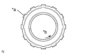 |
Check the rotating direction of the one-way clutch assembly for the lock or free operation as shown in illustration.
| *a | Groove |
| *b | Free |
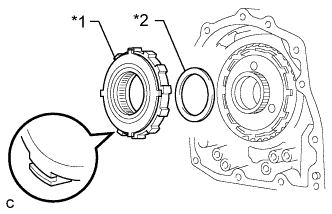 |
Install the one-way clutch assembly and No. 2 thrust washer to the rear planetary gear assembly.
| Item | Inside | Outside |
| Bearing | 53.6 mm (2.110 in.) | 69.6 mm (2.740 in.) |
| *1 | One-way Clutch Assembly |
| *2 | No. 2 Thrust Washer |
| 13. INSTALL REAR PLANETARY SUN GEAR ASSEMBLY |
Apply MP grease to the No. 1 thrust washer.
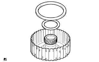 |
Install the No. 1 thrust washer and one-way clutch thrust bearing to the rear planetary sun gear assembly.
Apply MP grease to the thrust bearing.
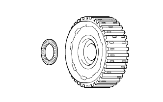 |
Install the thrust bearing to the rear planetary sun gear assembly.
| Item | Inside | Outside |
| Bearing | 33.7 mm (1.327 in.) | 48.2 mm (1.898 in.) |
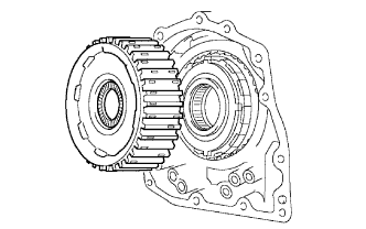 |
Install the rear planetary sun gear assembly to the transaxle case.
| 14. INSTALL 2ND BRAKE PISTON O-RING |
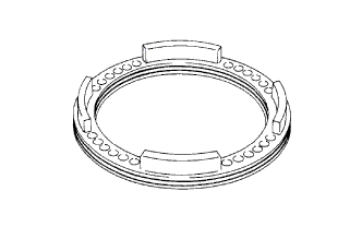 |
Coat 2 new 2nd brake piston O-rings with ATF and install them into the 2nd brake piston.
| 15. INSTALL 2ND BRAKE PISTON |
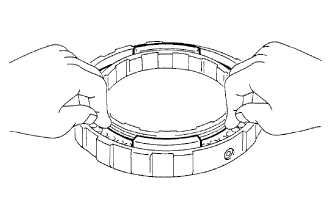 |
Press the 2nd brake piston into the 2nd brake cylinder with your hands.
| 16. INSTALL 2ND BRAKE PISTON RETURN SPRING SUB-ASSEMBLY |
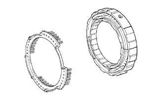 |
Install the 2nd brake piston return spring sub-assembly to the 2nd brake piston.
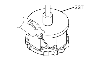 |
Place SST on the 2nd brake piston return spring sub-assembly, and compress the 2nd brake piston return spring sub-assembly with a press.
Using a screwdriver, install the snap ring.
| 17. INSTALL 2ND BRAKE PISTON ASSEMBLY |
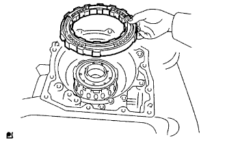 |
Install the 2nd brake piston assembly to the transaxle case.
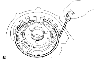 |
Using a screwdriver, install the snap ring to the transaxle case.
| 18. INSTALL 2ND BRAKE CLUTCH DISC |
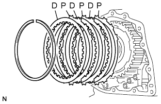 |
Install the 3 2nd brake clutch discs and 3 plates to the transaxle case.
Temporarily install the snap ring.
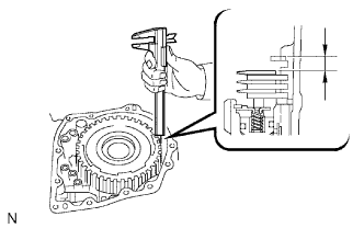 |
Using a vernier caliper, measure the distance between the 2nd brake clutch disc and snap ring surface.
Select an appropriate flange so that the piston stroke will meet the specified value.
| Mark | Thickness | Mark | Thickness |
| 0 | 2.9 mm (0.114 in.) | 5 | 3.4 mm (0.134 in.) |
| 1 | 3.0 mm (0.118 in.) | 6 | 3.5 mm (0.138 in.) |
| 2 | 3.1 mm (0.122 in.) | 7 | 3.6 mm (0.142 in.) |
| 3 | 3.2 mm (0.126 in.) | 8 | 3.7 mm (0.146 in.) |
| 4 | 3.3 mm (0.130 in.) | - | - |
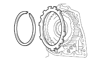 |
Temporarily remove the snap ring, attach the selected flange and restore the snap ring.
| 19. INSTALL DIRECT CLUTCH RETURN SPRING SUB-ASSEMBLY |
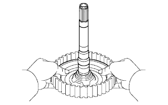 |
Coat the direct clutch piston with ATF, and install it to the direct clutch drum.
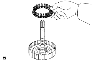 |
Install the direct clutch return spring sub-assembly to the direct clutch drum.
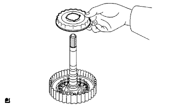 |
Coat the clutch balancer with ATF, and install it to the direct clutch drum.
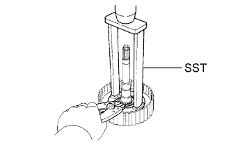 |
Place SST on the clutch balancer and compress the return spring with a press.
Using a snap ring expander, install the snap ring to the direct clutch drum.
| 20. INSTALL DIRECT MULTIPLE DISC CLUTCH DISC SNAP RING |
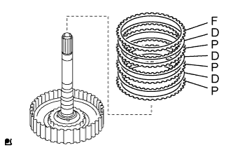 |
Install the 3 plates, 3 discs and flange.
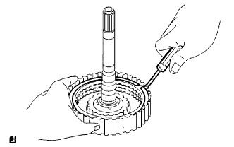 |
Using a screwdriver, install the direct multiple disc clutch disc snap ring.
Check that the end gap of the direct multiple disc clutch disc snap ring is not aligned with any one of the cutouts.
| 21. INSPECT PACK CLEARANCE OF DIRECT CLUTCH |
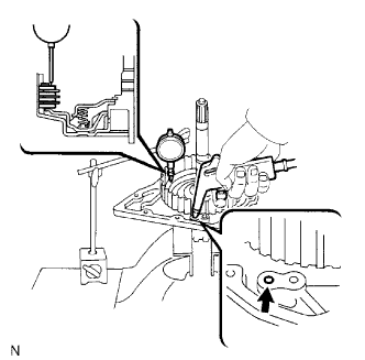 |
Install the direct clutch and needle roller bearing on the transaxle rear cover.
Using a dial indicator, measure the direct clutch pack clearance while applying and releasing compressed air (392 kPa, 4.0 kgf/cm2, 57 psi).
| Mark | Thickness | Mark | Thickness |
| 0 | 2.9 mm (0.114 in.) | 4 | 3.3 mm (0.130 in.) |
| 1 | 3.0 mm (0.118 in.) | 5 | 3.4 mm (0.134 in.) |
| 2 | 3.1 mm (0.122 in.) | 6 | 3.5 mm (0.138 in.) |
| 3 | 3.2 mm (0.126 in.) | 7 | 3.6 mm (0.142 in.) |
| 22. INSPECT DIRECT MULTIPLE DISC CLUTCH DISC |
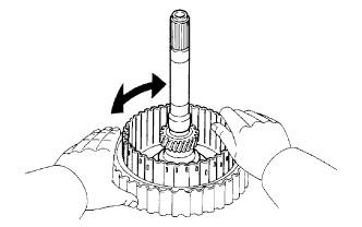 |
Inspect the clutch disc rotation.
Check that the disc rotates when rotating the disc after inserting the rear planetary sun gear.
| 23. INSTALL DIRECT CLUTCH ASSEMBLY |
Apply MP grease to the bearing race.
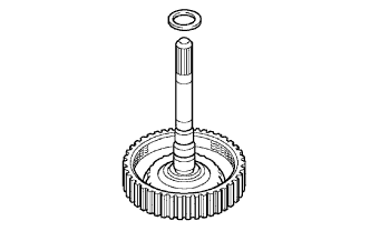 |
Install the bearing race to the direct clutch assembly.
| Item | Inside | Outside |
| Bearing race | 30.3 mm (1.193 in.) | 46.2 mm (1.819 in.) |
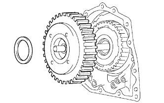 |
Install the direct clutch assembly and thrust needle roller bearing to the transaxle case.
 |
Clean the connector part of the transaxle case and rear transaxle cover sub-assembly.
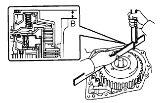
As shown in the illustration, place a straightedge on the direct clutch drum and measure the distance between the transaxle case and the straightedge using a vernier caliper (Dimension B).
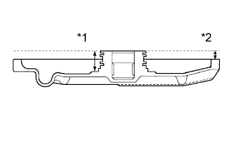 |
Measure the 2 places of the rear transaxle cover sub-assembly as shown in the illustration and calculate dimension C using the following formula.
| *1 | Dimension (1) |
| *2 | Dimension (2) |
Calculate the end play value using the following formula. Select a thrust bearing which satisfies the end play value and install it.
| Thickness | Inside | Outside |
| 3.58 mm (0.1409 in.) | 53.6 mm (2.110 in.) | 69.6 mm (2.740 in.) |
| 3.88 mm (0.1528 in.) | 53.6 mm (2.110 in.) | 70.18 mm (2.763 in.) |
| 24. INSTALL O-RING |
Coat 2 new O-rings with ATF, and install it to the transaxle case.
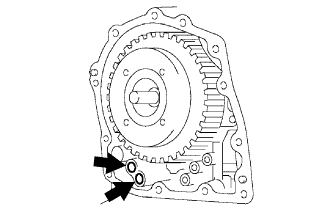 |
Install 2 new O-rings to the transaxle case.
| 25. INSTALL FRONT CLUTCH APPLY TUBE |
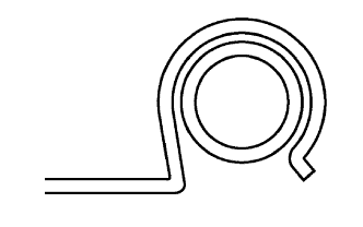 |
Install the apply pump clamp to the front clutch apply tube.
| 26. INSTALL BRAKE APPLY TUBE |
|
Install the apply pump clamp to the brake apply tube.
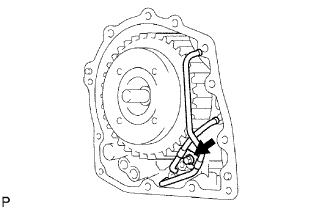 |
Install the 2 apply tubes to the transaxle case with the bolt.
| 27. INSTALL NO. 1 TRANSAXLE CASE PLUG |
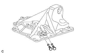 |
Coat 2 new O-rings with ATF, and install them to the 2 No. 1 transaxle case plugs.
Install the 2 No. 1 transaxle case plugs to the rear transaxle cover sub-assembly.
| 28. INSTALL REAR TRANSAXLE COVER SUB-ASSEMBLY |
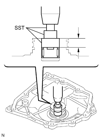 |
Using SST and a press, press in a new needle roller bearing.
Clean and degrease the screws and screw holes.
Apply adhesive to the 2 screws.
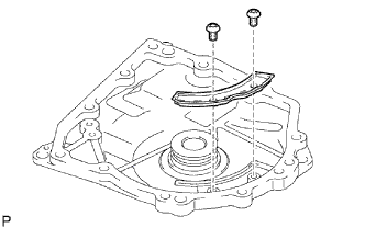 |
Using a T30 ''TORX'' socket, install the plate with the 2 screws.
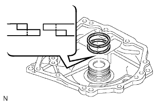 |
Install the 2 new outer rear clutch oil seal rings to the rear transaxle cover sub-assembly.
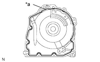 |
Remove any packing material and be careful not to get oil on the contacting surfaces of the rear transaxle cover sub-assembly or the transaxle case.
| *a | Seal Packing |
Apply seal packing to the rear transaxle cover sub-assembly.
Coat the needle roller bearing with ATF.
Clean and degrease the bolt holes.
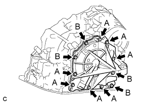 |
Apply adhesive to the threads of new bolts labeled A.
Install the 11 bolts.
| 29. INSTALL UNDERDRIVE CLUTCH DRUM OIL SEAL RING |
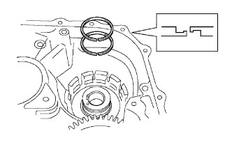 |
Install 2 new underdrive clutch drum oil seal rings to the transaxle case.
| 30. INSTALL UNDERDRIVE BRAKE PISTON |
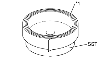 |
Wrap vinyl tape around SST 4.0 mm (0.157 in.) above the bottom end until the thickness of the wrapped tape is about 5.0 mm (0.197 in.).
| *1 | Vinyl Tape |
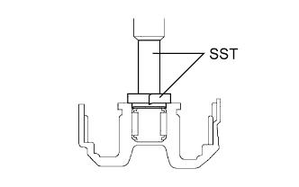 |
Using SST and a press, press a new needle roller bearing into the transaxle case until the vinyl tape contacts the transaxle case.
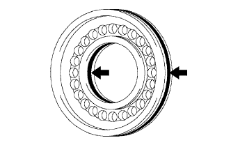 |
Coat 2 new O-rings with ATF, and install them to the underdrive brake piston.
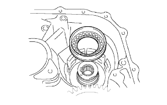 |
Install the underdrive brake piston to the transaxle case.
| 31. INSTALL UNDERDRIVE BRAKE RETURN SPRING SUB-ASSEMBLY |
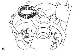 |
Install the underdrive brake return spring sub-assembly to the underdrive brake piston.
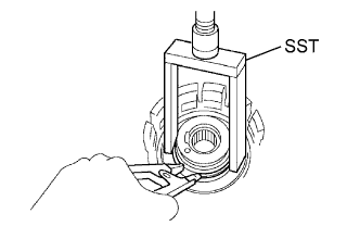 |
Using SST, a snap ring expander and press, press the underdrive brake return spring sub-assembly and install the snap ring to the transaxle case.
| 32. INSTALL NO. 2 UNDERDRIVE CLUTCH DISC |
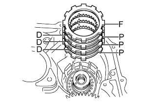 |
Install the flange, 3 No. 2 underdrive clutch discs and 3 plates to the transaxle case.
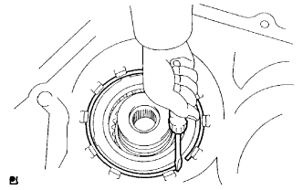 |
Using a screwdriver, install the snap ring.
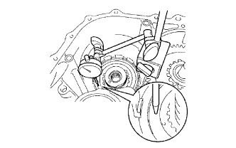 |
Using a dial indicator, measure the underdrive brake piston stroke while applying and releasing compressed air (392 kPa, 4.0 kgf/cm2, 57 psi).
| Mark | Thickness | Mark | Thickness |
| F | 2.8 mm (0.110 in.) | C | 3.4 mm (0.134 in.) |
| A | 3.0 mm (0.118 in.) | D | 3.6 mm (0.142 in.) |
| B | 3.2 mm (0.126 in.) | - | - |
Temporarily remove the snap ring and attach the flange. Restore the snap ring.
| 33. INSTALL UNDERDRIVE ONE-WAY CLUTCH ASSEMBLY |
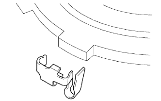 |
Install the outer race retainer to the underdrive one-way clutch assembly.
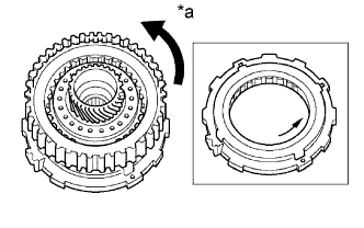 |
Install the underdrive clutch assembly to the one-way clutch assembly. Rotate the underdrive clutch assembly to check the rotating direction for the lock or free operation.
| *a | Free |
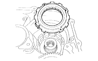 |
Install the underdrive one-way clutch assembly to the transaxle case.
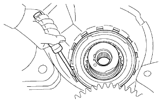 |
Using a screwdriver, install the snap ring to the transaxle case.
| 34. INSTALL UNDERDRIVE CLUTCH DRUM O-RING |
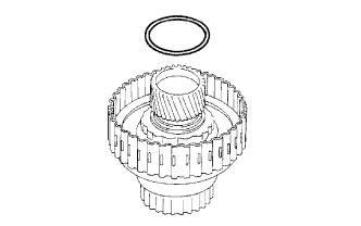 |
Coat a new underdrive clutch drum O-ring with ATF and install it to the underdrive clutch drum sub-assembly.
| 35. INSTALL UNDERDRIVE CLUTCH PISTON SET |
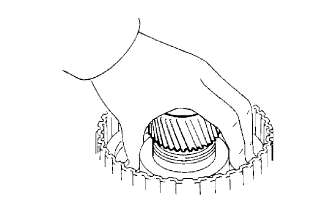 |
Coat the underdrive clutch piston with ATF, and install it to the underdrive clutch drum sub-assembly.
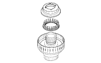 |
Install the underdrive clutch return spring sub-assembly and clutch balancer to the underdrive clutch drum sub-assembly.
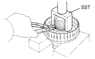 |
Place SST on the clutch balancer and compress the spring with a press.
Using a snap ring expander, install the snap ring to the underdrive clutch drum sub-assembly.
| 36. INSTALL NO. 1 UNDERDRIVE CLUTCH DISC SNAP RING |
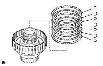 |
Install the 3 plates, 3 discs and flange.
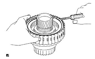 |
Using a screwdriver, install the No. 1 underdrive clutch disc snap ring to the underdrive clutch drum sub-assembly.
Check that the end gap of the No. 1 underdrive clutch disc snap ring is not aligned with one of the cutouts.
| 37. INSPECT UNDERDRIVE CLUTCH PACK CLEARANCE |
Install the underdrive clutch to the transaxle case.
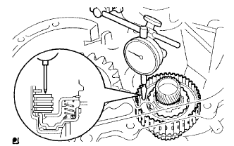 |
Install a dial indicator as shown in the illustration.
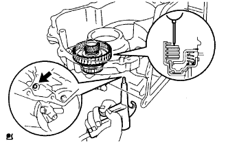 |
Measure the underdrive clutch piston stroke while applying and releasing compressed air (392 kPa, 4.0 kgf/cm2, 57 psi).
| Mark | Thickness | Mark | Thickness |
| A | 3.0 mm (0.118 in.) | G | 3.1 mm (0.122 in.) |
| B | 3.2 mm (0.126 in.) | H | 3.3 mm (0.130 in.) |
| C | 3.4 mm (0.134 in.) | J | 3.5 mm (0.138 in.) |
| F | 2.9 mm (0.114 in.) | - | - |
| 38. INSTALL UNDERDRIVE CLUTCH ASSEMBLY |
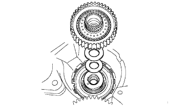 |
Coat the needle roller bearing and No. 3 thrust bearing underdrive race with MP grease, and install them onto the underdrive clutch assembly.
| Item | Inside | Outside |
| Bearing | 37.73 mm (1.4854 in.) | 58.0 mm (2.283 in.) |
| Race | 29.9 mm (1.177 in.) | 55.5 mm (2.185 in.) |
Install the underdrive clutch assembly to the transaxle case.
| 39. INSTALL UNDERDRIVE PLANETARY RING GEAR |
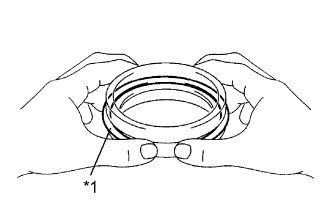 |
Install a new counter drive gear hole snap ring to the underdrive angular ball bearing outer race of the underdrive angular ball bearing.
| *1 | Snap Ring |
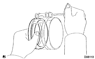 |
Using a piston ring compressor, squeeze the counter drive gear hole snap ring.
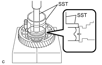 |
Using SST and a press, press in the underdrive angular ball bearing outer race of the underdrive angular ball bearing.
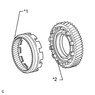 |
Install the underdrive planetary ring gear to the counter driven gear.
| *1 | Underdrive Planetary Ring Gear |
| *2 | Counter Driven Gear |
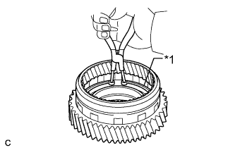 |
Using snap ring pliers, install the underdrive planetary ring hole snap ring.
| *1 | Underdrive Planetary Ring Hole Snap Ring |
| 40. INSTALL UNDERDRIVE PLANETARY GEAR ASSEMBLY |
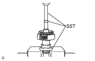 |
Using SST and a press, press the underdrive angular ball bearing inner race (rear side) into the underdrive planetary gear assembly.
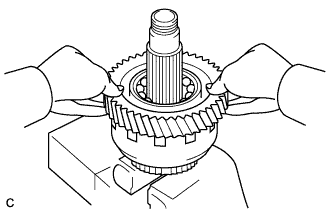 |
Install the counter driven gear with underdrive planetary ring gear to the underdrive planetary gear assembly.
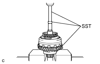 |
Using SST and a press, press in the underdrive angular ball bearing inner race (front side).
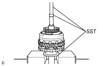 |
Using SST and a press, press in the parking lock gear.
| 41. INSTALL DIFFERENTIAL DRIVE PINION |
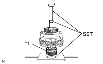 |
Using SST and a press, press in the differential drive pinion.
| *1 | Differential Drive Pinion |
| 42. INSTALL CYLINDRICAL ROLLER BEARING INNER RACE |
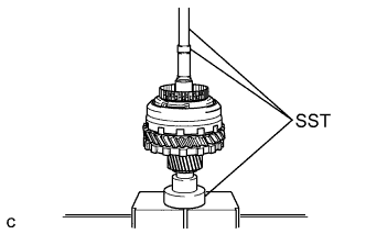 |
Using SST and a press, press in the cylindrical roller bearing inner race.
| 43. INSTALL FRONT PLANETARY GEAR NUT |
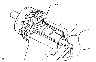 |
Clamp the underdrive planetary gear in a soft jaw vise.
| *1 | Underdrive Planetary Gear |
Using a socket wrench, install a new gear nut.
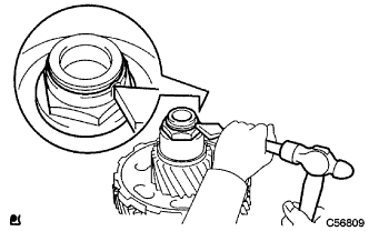 |
Using a chisel and hammer, stake the gear nut.
| 44. INSTALL UNDERDRIVE PLANETARY GEAR ASSEMBLY |
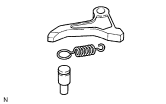 |
Install the parking lock pawl pin and tension spring to the parking lock pawl.
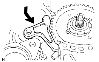 |
Temporarily install the parking lock pawl, parking lock pawl shaft and tension spring to the transaxle case as shown in the illustration.
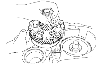 |
Install the underdrive planetary gear assembly to the transaxle case.
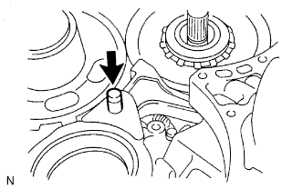 |
Install the parking lock pawl shaft to the transaxle case.
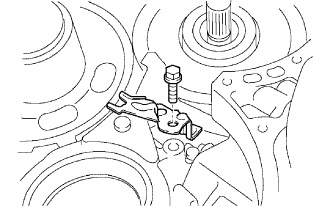 |
Install the parking lock pawl shaft clamp to the transaxle case with the bolt.
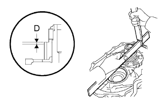 |
Using a straightedge and vernier caliper as shown in the illustration, measure the gap between the top of the differential drive pinion in the underdrive planetary gear and contact surface of the transaxle and housing (Dimension D).
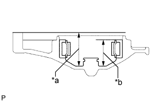 |
As shown in the illustration, measure the 2 places of the transaxle housing. Calculate dimension E using the formula.
| *a | Dimension (1) |
| *b | Dimension (2) |
| 45. INSPECT MULTIPLE DISC CLUTCH HUB |
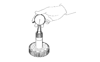 |
Using a caliper gauge, measure the inside diameter of the multiple disc clutch hub.
| 46. INSTALL MULTIPLE DISC CLUTCH HUB |
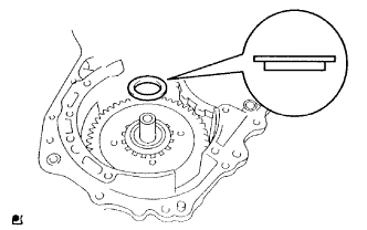 |
Install the bearing race to the transaxle case while checking its direction.
| Item | Inside | Outside |
| Bearing race | 34.5 mm (1.358 in.) | 48.5 mm (1.909 in.) |
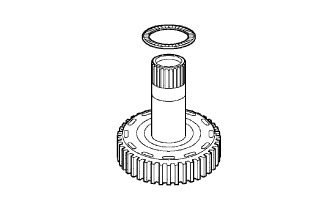 |
Install the thrust needle roller bearing to the multiple disc clutch hub.
| Item | Inside | Outside |
| Bearing | 36.3 mm (1.429 in.) | 52.25 mm (2.055 in.) |
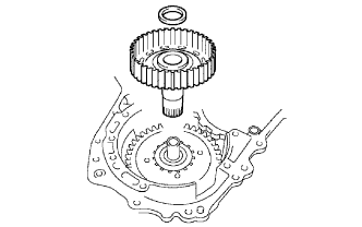 |
Install the thrust bearing to the multiple disc clutch hub.
| Item | Inside | Outside |
| Bearing | 23.5 mm (0.925 in.) | 44.0 mm (1.732 in.) |
Install the multiple disc clutch hub to the transaxle case.
| 47. INSTALL INPUT SHAFT OIL SEAL RING |
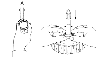 |
Compress the input shaft oil seal ring from both sides to reduce dimension A.
Coat the input shaft oil seal ring with ATF and install it to the forward clutch drum.
| 48. INSTALL FORWARD CLUTCH PISTON O-RING |
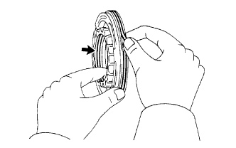 |
Coat 2 new forward clutch piston O-rings with ATF, and install them to the forward clutch piston sub-assembly.
| 49. INSTALL FORWARD CLUTCH PISTON SUB-ASSEMBLY |
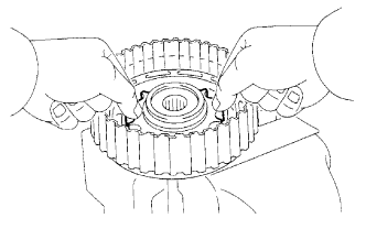 |
Install the forward clutch piston sub-assembly to the forward clutch drum.
| 50. INSTALL FORWARD CLUTCH RETURN SPRING SUB-ASSEMBLY |
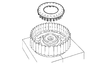 |
Place the forward clutch return spring sub-assembly onto the forward clutch piston sub-assembly.
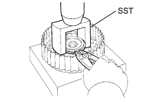 |
Place SST on the forward clutch return spring sub-assembly, and compress the forward clutch return spring sub-assembly with a press.
Install the snap ring with a snap ring expander. Be sure that the end gap of the snap ring is not aligned with the spring retainer claw.
| 51. INSTALL FORWARD CLUTCH FLANGE HOLE SNAP RING |
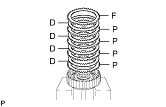 |
Install the 4 plates, 4 forward multiple disc clutch discs and flange.
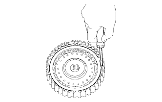 |
Using a screwdriver, install the forward clutch flange hole snap ring.
Check that the end gap of the forward clutch flange hole snap ring is not aligned with one of the cutouts.
| 52. INSPECT PACK CLEARANCE OF FORWARD CLUTCH |
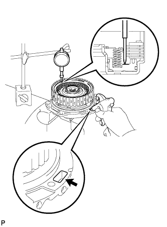 |
Install the forward clutch on the oil pump.
Using a dial indicator, measure the forward clutch piston stroke while applying and releasing compressed air (392 kPa, 4.0 kgf/cm2, 57 psi).
| Mark | Thickness | Mark | Thickness |
| 0 | 2.85 mm (0.112 in.) | 4 | 3.45 mm (0.1358 in.) |
| 1 | 3.00 mm (0.1181 in.) | 5 | 3.60 mm (0.1417 in.) |
| 2 | 3.15 mm (0.1240 in.) | 6 | 3.75 mm (0.147 in.) |
| 3 | 3.30 mm (0.1299 in.) | - | - |
| 53. INSPECT FORWARD MULTIPLE DISC CLUTCH DISC |
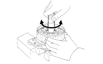 |
Inspect the forward multiple disc clutch disc rotation.
After inserting the multiple disc clutch into the multiple disc clutch hub, rotate the forward clutch and check that the disc lightly rotates.
| 54. INSTALL FORWARD CLUTCH ASSEMBLY |
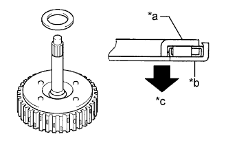 |
Install the thrust bearing to the forward clutch assembly.
| Item | Inside | Outside |
| Bearing | 33.85 mm (1.3327 in.) | 52.2 mm (2.055 in.) |
| *a | Race "B" |
| *b | Race "A" |
| *c | Forward Clutch Side |
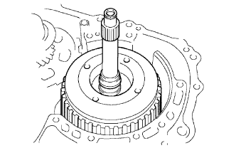 |
Install the forward clutch assembly to the transaxle case.
| 55. INSTALL O-RING |
Coat 2 new O-rings with ATF, and install it to the transaxle case.
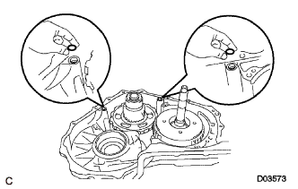 |
Install 2 new O-rings to the transaxle case.
| 56. INSTALL FRONT DIFFERENTIAL ASSEMBLY |
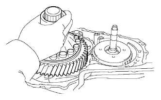 |
Install the front differential assembly to the transaxle case.
| 57. INSTALL NO. 2 THRUST BEARING UNDERDRIVE RACE |
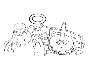 |
Install the No. 2 thrust bearing underdrive race to the underdrive planetary gear assembly.
| 58. INSTALL THRUST NEEDLE ROLLER BEARING |
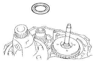 |
Calculate the end play value using the following formula and value of dimensions D and E that were measured when installing the cylindrical roller bearing and underdrive planetary gear. Select an appropriate No. 2 thrust bearing underdrive race which satisfies the specified end play value, and install it.
| E - D | Thickness |
| Less than 7.34 mm (0.2890 in.) | 3.5 mm (0.138 in.) |
| 7.34 mm (0.2890 in.) | 3.8 mm (0.150 in.) |
| Item | Inside | Outside |
| Bearing | 53.0 mm (2.087 in.) | 78.2 mm (3.079 in.) |
| Bearing race | 52.1 mm (2.051 in.) | 75.5 mm (2.972 in.) |
| 59. INSTALL OIL PUMP ASSEMBLY |
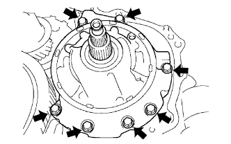 |
Install the oil pump assembly to the transaxle case with the 7 bolts.
| 60. INSTALL UNDERDRIVE OUTPUT SHAFT OIL SEAL RING |
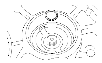 |
Install a new underdrive output shaft oil seal ring to the transaxle housing.
| 61. INSTALL UNDERDRIVE CYLINDRICAL ROLLER BEARING |
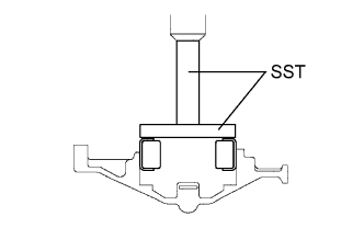 |
Using SST and a press, press in the underdrive cylindrical roller bearing.
| 62. INSTALL TRANSAXLE HOUSING |
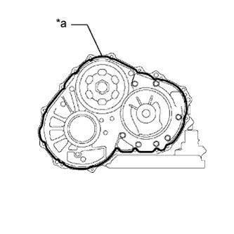 |
Remove any packing material and be careful not to get oil on the contacting surfaces of the transaxle case or transaxle housing.
| *a | Seal Packing |
Apply seal packing (Diameter 1.2 mm (0.0472 in.)) to the transaxle case.
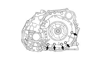 |
Clean and degrease the installation bolt holes.
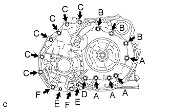 |
Install the transaxle housing to the transaxle case with the 18 bolts.
| 63. INSPECT INPUT SHAFT END PLAY |
Secure the transaxle case with the oil pump side facing up.
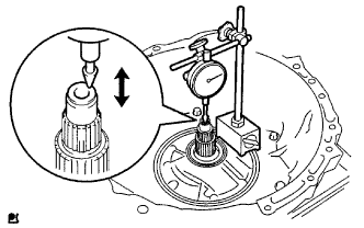 |
Using a dial indicator, measure the input shaft end play.
| 64. PLACE AUTOMATIC TRANSAXLE ASSEMBLY |
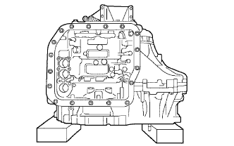 |
Place the automatic transaxle assembly on wooden blocks.
| 65. INSTALL MANUAL VALVE LEVER SHAFT OIL SEAL |
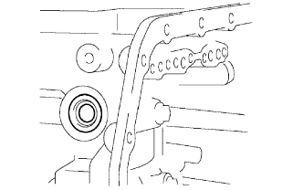 |
Coat a new manual valve lever shaft oil seal with ATF, and install it to the transaxle case.
| 66. INSTALL PARKING LOCK ROD SUB-ASSEMBLY |
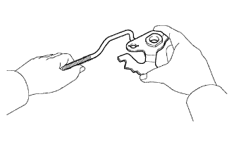 |
Install the parking lock rod sub-assembly to the manual valve lever sub-assembly.
| 67. INSTALL MANUAL VALVE LEVER SUB-ASSEMBLY |
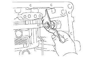 |
Install a new spacer and manual valve lever shaft to the transaxle case.
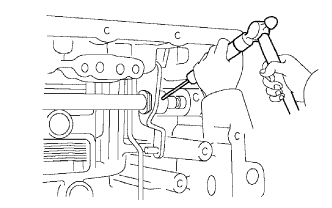 |
Using a pin punch (3 mm) and hammer, tap in a new pin.
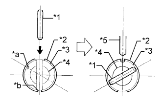 |
Turn the spacer and lever shaft to align the small hole for locating the staking position in the spacer with the staking position mark on the manual valve lever sub-assembly.
| *1 | Pin |
| *2 | Spacer |
| *3 | Manual Valve Lever Sub-assembly |
| *4 | Manual Valve Lever Shaft |
| *5 | Pin Punch |
| *a | Staking Position Mark |
| *b | Small Hole |
Using a pin punch, stake the spacer through the small hole.
Check that the spacer does not turn.
| 68. INSTALL MANUAL VALVE LEVER SHAFT RETAINER SPRING |
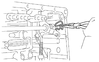 |
Using needle-nose pliers, install the manual valve lever shaft retainer spring.
| 69. INSTALL PARKING LOCK PAWL BRACKET |
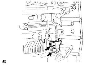 |
Install the parking lock pawl bracket to the transaxle case with the 2 bolts.
| 70. INSTALL MANUAL DETENT SPRING SUB-ASSEMBLY |
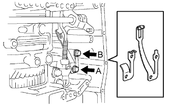 |
Install the manual detent spring sub-assembly and spring cover to the transaxle case with the 2 bolts.
| 71. INSTALL B-3 ACCUMULATOR PISTON |
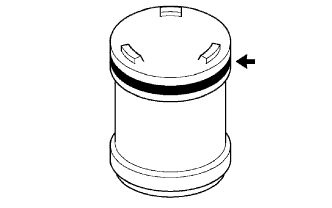 |
Coat a new O-ring with ATF, and install it to the B-3 accumulator piston.
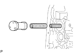 |
Coat the accumulator B-3 piston and 2 springs with ATF, and install them to the transaxle case.
| Spring | Free Length Outer Diameter | Color |
| B-3 Inner | 60.24 mm (2.3716 in.) 15.9 mm (0.626 in.) | Yellowish green |
| B-3 Outer | 74.61 mm (2.9374 in.) 21.7 mm (0.854 in.) | Blue |
| 72. INSTALL C-1 ACCUMULATOR PISTON |
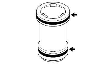 |
Coat 2 new O-rings and spring with ATF, and install them to the C-1 accumulator piston.
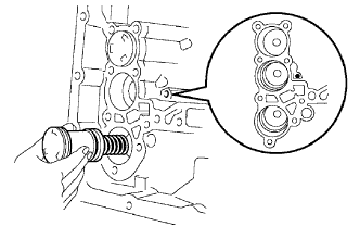 |
Coat the C-1 accumulator piston with ATF, and install it to the transaxle case.
| Spring | Free Length Outer Diameter | Color |
| C-1 | 81.53 mm (3.2098 in.) 18.5 mm (0.728 in.) | Pink |
| 73. INSTALL C-3 ACCUMULATOR PISTON |
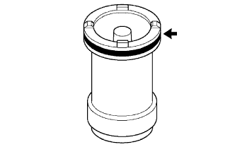 |
Coat a new O-ring with ATF, and install it to the C-3 accumulator piston.
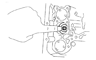 |
Coat the C-3 accumulator piston with ATF, and install it to the transaxle case.
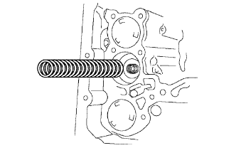 |
Install the spring to the C-3 accumulator piston.
| 74. INSTALL CHECK BALL BODY |
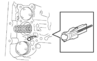 |
Install the check ball body and spring to the transaxle case.
| 75. INSTALL TRANSMISSION WIRE |
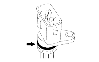 |
Coat a new O-ring with ATF, and install it to the transmission wire.
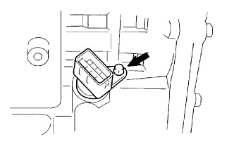 |
Install the transmission wire with the bolt.
| 76. INSTALL BRAKE DRUM GASKET |
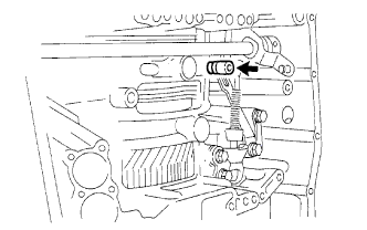 |
Coat a new brake drum gasket with ATF, and install it to the transaxle case.
| 77. INSTALL TRANSAXLE CASE 2ND BRAKE GASKET |
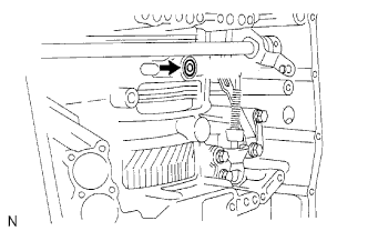 |
Coat a new transaxle case 2nd brake gasket with ATF, and install it to the transaxle case.
| 78. INSTALL NO. 1 GOVERNOR APPLY GASKET |
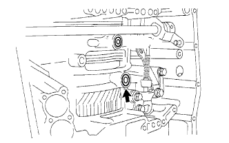 |
Coat a new No. 1 governor apply gasket with ATF, and install it to the transaxle case.
| 79. INSTALL TRANSMISSION VALVE BODY ASSEMBLY |
Coat the 17 bolts with ATF.
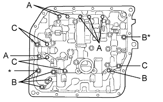 |
Verify that the manual valve lever is in the correct position, install the transmission valve body assembly to the transaxle case with the 17 bolts.
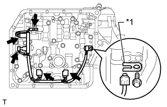 |
Connect the 5 connectors to the shift solenoid valves.
Install the ATF temperature sensor with the lock plate and bolt.
| *1 | Lock Plate |
| 80. INSTALL VALVE BODY OIL STRAINER ASSEMBLY |
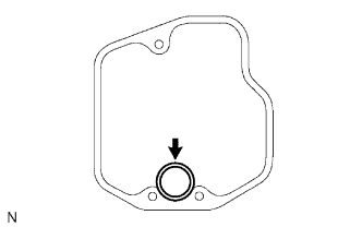 |
Coat a new O-ring with ATF, and install it to the valve body oil strainer assembly.
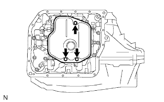 |
Install the valve body oil strainer assembly to the transmission valve body assembly with the 3 bolts.
| 81. INSTALL AUTOMATIC TRANSAXLE OIL PAN SUB-ASSEMBLY |
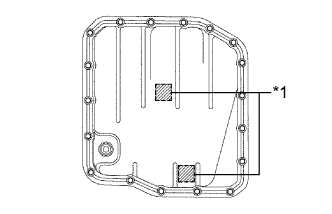 |
Install the 2 magnets in the automatic transaxle oil pan sub-assembly.
| *1 | Magnet |
Clean and degrease the bolt holes.
Apply adhesive to 18 new bolts.
Install a new gasket and the automatic transaxle oil pan sub-assembly with the 18 bolts.
| 82. INSTALL SPEED SENSOR |
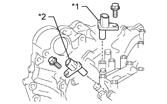 |
Install the speed sensor NC.
| *1 | Speed Sensor NC |
| *2 | Speed Sensor NT |
Coat a new O-ring with ATF and install it to the speed sensor NC.
Install the speed sensor NC to the transaxle case with a new bolt.
Install the speed sensor NT.
Coat a new O-ring with ATF and install it to the speed sensor NT.
Install the speed sensor NT to the transaxle case with the bolt.
| 83. INSTALL OIL COOLER INLET TUBE UNION |
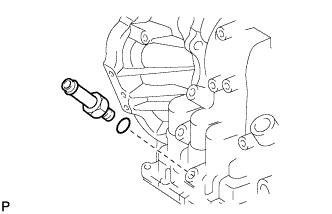 |
Coat a new O-ring with ATF, and install it to the oil cooler inlet tube union.
Install the oil cooler inlet tube union to the transaxle case.
| 84. INSTALL OIL COOLER OUTLET TUBE UNION |
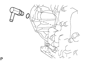 |
Coat a new O-ring with ATF, and install it to the oil cooler outlet tube union.
Install the oil cooler outlet tube union to the transaxle case.
| 85. INSTALL NO. 1 TRANSAXLE CASE PLUG |
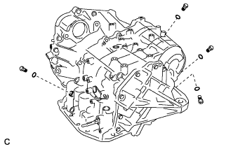 |
Coat 4 new O-rings with ATF, and install them to the 4 No. 1 transaxle case plugs.
Install the 4 No. 1 transaxle case plugs to the transaxle case.
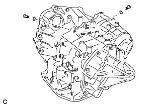 |
Coat 2 new O-rings with ATF, and install them to the 2 No. 1 transaxle case plugs.
Install the 2 No. 1 transaxle case plugs to the transaxle housing.
| 86. INSTALL NO. 2 BREATHER PLUG |
Coat a new O-ring with ATF, and install it to the No. 2 breather plug.
Install the No. 2 breather plug to the transaxle case.
| 87. INSTALL NO. 1 BREATHER PLUG |
Install the No. 1 breather plug to the breather plug hose.
| 88. INSTALL BREATHER PLUG HOSE |
Install the breather plug hose to the No. 2 breather plug.
| 89. INSTALL PARK/NEUTRAL POSITION SWITCH ASSEMBLY |
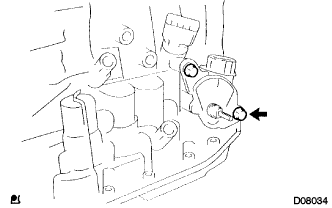 |
Install the park/neutral position switch assembly onto the manual valve lever shaft and temporarily install the 2 adjusting bolts.
Install a new lock plate and the lock nut.
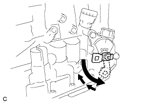 |
Temporarily install the control shaft lever to the manual valve lever shaft.
Turn the lever counterclockwise until it stops, and then turn it clockwise 2 notches.
Remove the control shaft lever from the manual valve lever shaft.
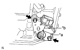 |
Align the nut stopper protrusion with the neutral basic line.
| *a | Nut Stopper Protrusion |
| *b | Neutral Basic Line |
Tighten the 2 bolts.
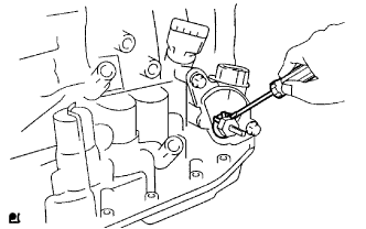 |
Using a screwdriver, stake the lock nut with the lock plate.
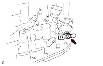 |
Install the control shaft lever, washer and nut to the manual valve lever shaft.
| 90. INSTALL SPEEDOMETER DRIVEN HOLE COVER SUB-ASSEMBLY |
Coat a new O-ring with ATF, and install it to the speedometer driven hole cover sub-assembly.
Install the speedometer driven hole cover sub-assembly with the bolt to the transaxle case.