Using a plastic hammer, tap in the ring pins.
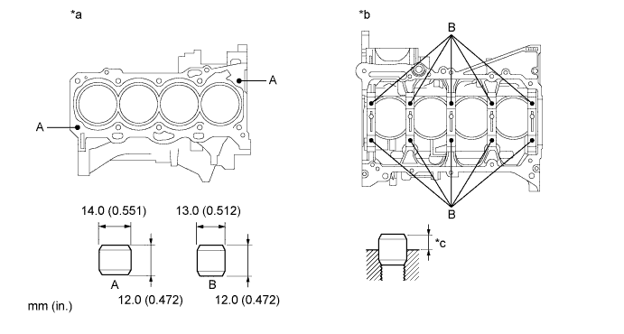
| *a | Upper Side | *b | Lower Side |
| *c | Protrusion Height | - | - |
- Standard Protrusion:
Item Protrusion A 6 mm (0.236 in.) B 5 mm (0.197 in.)
CYLINDER BLOCK > REASSEMBLY |
| 1. INSTALL RING PIN |
Using a plastic hammer, tap in the ring pins.
| *a | Upper Side | *b | Lower Side |
| *c | Protrusion Height | - | - |
| Item | Protrusion |
| A | 6 mm (0.236 in.) |
| B | 5 mm (0.197 in.) |
| 2. INSTALL STUD BOLT |
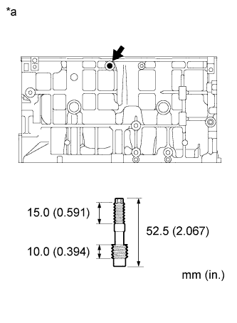 |
Using an E7 "TORX" socket, install the stud bolt.
| *a | RH Side |
| 3. INSTALL STRAIGHT PIN |
Using a plastic hammer, tap in the straight pins.
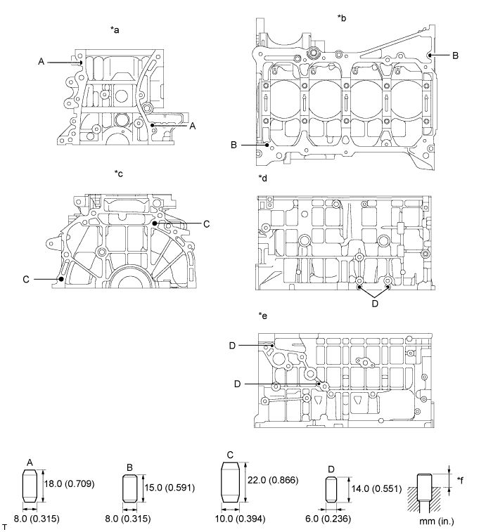
| *a | Front Side | *b | Lower Side |
| *c | Rear Side | *d | RH Side |
| *e | LH Side | *f | Protrusion Height |
| Item | Protrusion |
| A | 8 mm (0.315 in.) |
| B | 7.5 mm (0.295 in.) |
| C | 12 mm (0.472 in.) |
| D | 5 mm (0.197 in.) |
| 4. INSPECT CRANKSHAFT OIL CLEARANCE |
Check the crank journal and bearing for pitting and scratches.
Install the crankshaft bearing .
Place the crankshaft on the cylinder block.
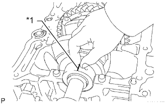 |
Lay a strip of plastigage across each journal.
| *1 | Plastigage |
Examine the front marks and numbers and install the crankshaft bearing caps on the cylinder block.
Install the crankshaft bearing caps .
Remove the bearing caps .
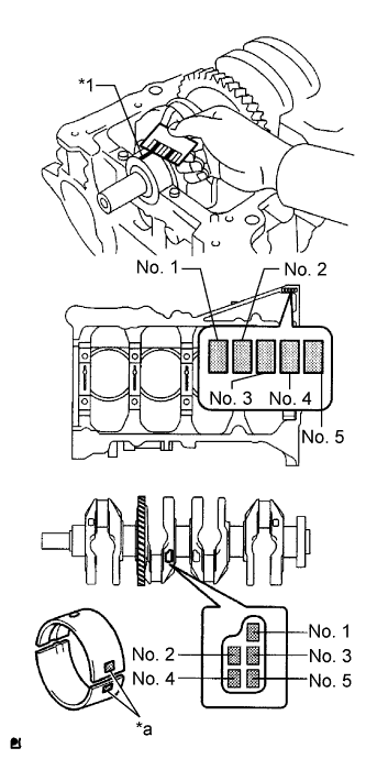 |
Measure the Plastigage at its widest point.
| *1 | Plastigage |
| *a | Number Mark |
| Cylinder block + Crankshaft | 0 to 2 | 3 to 5 | 6 to 8 | 9 to 11 |
| Bearing to be used | "1" | "2" | "3" | "4" |
| Mark | Specified Condition |
| 0 | 59.000 to 59.002 mm (2.32283 to 2.32291 in.) |
| 1 | 59.003 to 59.004 mm (2.32295 to 2.32299 in.) |
| 2 | 59.005 to 59.006 mm (2.32303 to 2.32307 in.) |
| 3 | 59.007 to 59.009 mm (2.32311 to 2.32318 in.) |
| 4 | 59.010 to 59.011 mm (2.32322 to 2.32326 in.) |
| 5 | 59.012 to 59.013 mm (2.32330 to 2.32334 in.) |
| 6 | 59.014 to 59.016 mm (2.32338 to 2.32346 in.) |
| Mark | Specified Condition |
| 0 | 54.999 to 55.000 mm (2.16531 to 2.16535 in.) |
| 1 | 54.997 to 54.998 mm (2.16523 to 2.16527 in.) |
| 2 | 54.995 to 54.996 mm (2.16515 to 2.16519 in.) |
| 3 | 54.993 to 54.994 mm (2.16507 to 2.16511 in.) |
| 4 | 54.991 to 54.992 mm (2.16500 to 2.16504 in.) |
| 5 | 54.988 to 54.990 mm (2.16488 to 2.16496 in.) |
| Mark | Specified Condition |
| 1 | 1.993 to 1.996 mm (0.078464 to 0.078583 in.) |
| 2 | 1.997 to 1.999 mm (0.078622 to 0.078701 in.) |
| 3 | 2.000 to 2.002 mm (0.078740 to 0.078819 in.) |
| 4 | 2.003 to 2.005 mm (0.078858 to 0.078937 in.) |
| 5. INSTALL PISTON |
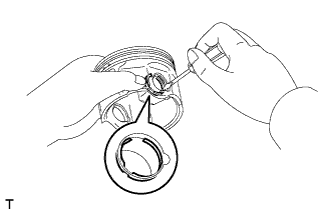 |
Using a screwdriver, install a new snap ring at one end of the piston pin hole.
Gradually heat the piston to approximately 80 to 90 °C (176 to 194°F).
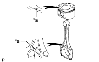 |
Align the front marks on the piston and connecting rod, and push in the piston with a thumb.
| *1 | Front Mark |
Using a screwdriver, install a new piston pin hole snap ring on the other end of the piston pin hole.
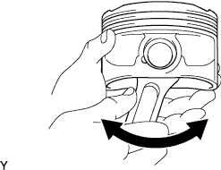 |
Check the fitting condition between the piston and piston pin by trying to move the piston back and forth on the piston pin.
| 6. INSTALL PISTON RING SET |
Install the oil ring expander and 2 oil ring side rails by hand.
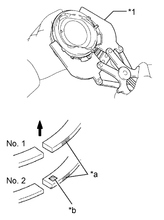 |
Using a piston ring expander, install the 2 compression rings.
| *1 | Piston Ring Expander |
| *a | Paint Mark |
| *b | Code Mark (T) |
 | Upward |
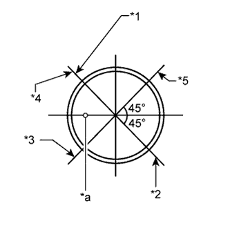 |
Position the piston rings so that the ring ends are as shown in the illustration.
| *1 | No. 1 Compression Ring |
| *2 | No. 2 Compression Ring |
| *3 | Upper Oil Ring Side Rail |
| *4 | Oil Ring Expander |
| *5 | Lower Oil Ring Side Rail |
| *a | Front Mark |
| 7. INSTALL CRANKSHAFT BEARING |
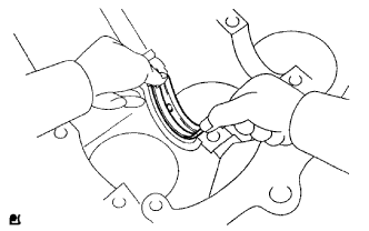 |
Install the upper bearing with an oil groove on the cylinder block.
| 8. INSTALL NO. 2 CRANKSHAFT BEARING |
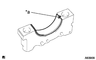 |
Install the No. 2 crankshaft bearing on the bearing cap.
| *a | Claw |
| 9. INSTALL UPPER CRANKSHAFT THRUST WASHER |
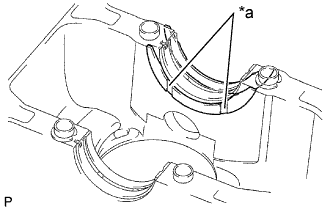 |
Install the 2 upper crankshaft thrust washers under the No. 3 journal of the cylinder block with the oil grooves facing outward.
| *a | Oil Groove |
Apply engine oil to the upper crankshaft thrust washers.
| 10. INSTALL CRANKSHAFT |
Apply engine oil to the crankshaft bearings and place the crankshaft on the cylinder block.
Apply engine oil to the No.2 crankshaft bearings.
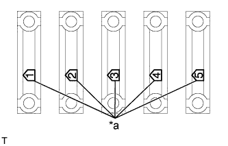 |
Examine the front marks and install the crankshaft bearing caps on the cylinder block.
| *a | Front Mark and Number |
Apply a light coat of engine oil to the threads and under the crankshaft bearing cap set bolts.
Install the crankshaft bearing cap set bolts.
Step 1
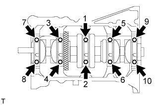 |
Retighten the 10 crankshaft bearing cap set bolts in the sequence shown in the illustration.
Step 2
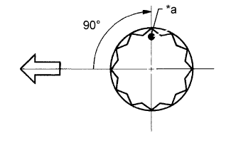 |
Mark the front of the crankshaft bearing cap set bolts with paint.
| *a | Paint Mark |
 | Engine Front |
Retighten the crankshaft bearing cap set bolts 90° in the numerical order shown in the illustration.
Check that the paint mark is now at a 90° angle to the front.
Check that the crankshaft turns smoothly.
Check the crankshaft thrust clearance .
| 11. INSTALL CONNECTING ROD BEARING |
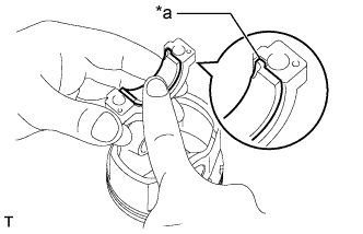 |
Align the bearing claw with the groove on the connecting rod or connecting rod cap.
| *a | Claw |
| 12. INSTALL PISTON SUB-ASSEMBLY WITH CONNECTING ROD |
Apply engine oil to the cylinder walls, pistons, and surfaces of connecting rod bearings.
|
Check the position of the piston ring ends.
| *1 | No. 1 Compression Ring |
| *2 | No. 2 Compression Ring |
| *3 | Upper Oil Ring Side Rail |
| *4 | Oil Ring Expander |
| *5 | Lower Oil Ring Side Rail |
| *a | Front Mark |
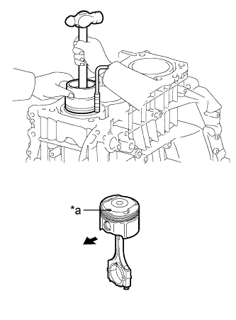 |
Using a piston ring compressor, push the correctly numbered piston and connecting rod assemblies into each cylinder with the front mark of the piston facing forward.
| *a | Front Mark |
| Engine Front |
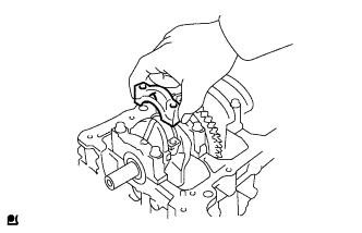 |
Check that the protrusion on the connecting rod cap is facing in the correct direction.
Apply a light coat of engine oil to the threads and under the heads of the connecting rod cap bolts.
Install the connecting rod cap bolts.
Step 1
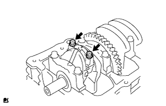 |
Install and alternately tighten the bolts of the connecting rod cap in several steps.
Step 2
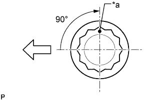 |
Mark the front of the connecting rod cap bolts with paint.
Retighten the cap bolts 90° as shown in the illustration.
| *a | Paint Mark |
| Engine Front |
Check that the crankshaft turns smoothly.
Check the connecting rod thrust clearance .