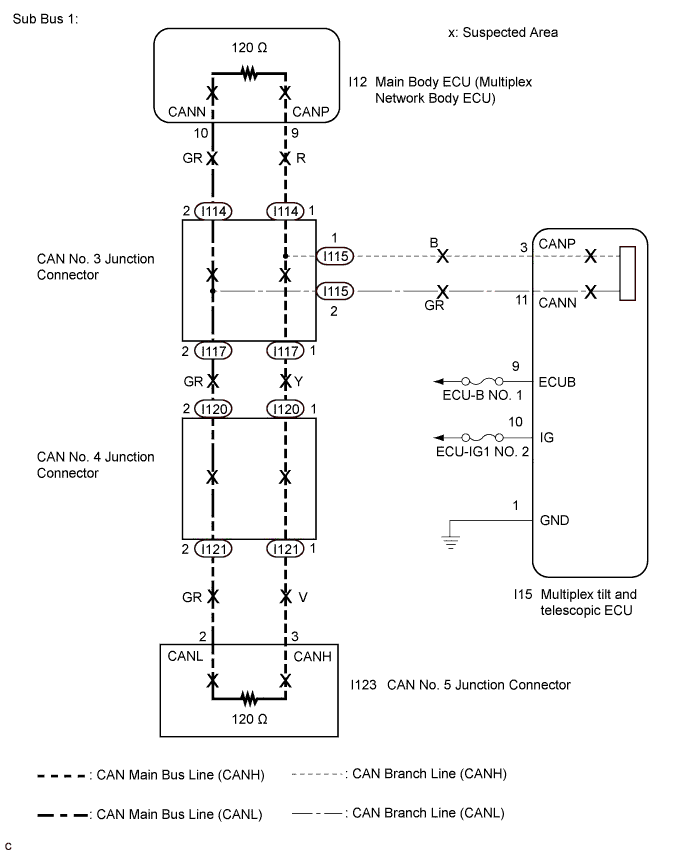
DTC U1002 Lost Communication with Gateway Module (Main Body ECU) |
DTC U1115 Lost Communication with Tilt and Telescopic Module |
| DTC No. | DTC Detection Condition | Trouble Area |
| U1002 | Main body ECU cannot receive signals from all ECUs that have been memorized as those connected to sub bus 1. |
|
| U1115 | No communication from the multiplex tilt and telescopic ECU |
|
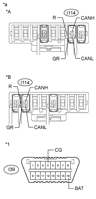
| 1.CHECK SUB BUS 1 |
 |
Disconnect the cable from the negative (-) battery terminal.
Measure the resistance according to the value(s) in the table below.
| Tester Connection | Condition | Specified Condition | Result |
| I114-1 (CANH) - I114-2 (CANL) | Cable disconnected from negative (-) battery terminal | 54 to 69 Ω | Below 54 Ω: Short circuit between bus lines |
| 70 Ω or higher: Open circuit in a main bus line | |||
| I114-1 (CANH) - I39-4 (CG) | Cable disconnected from negative (-) battery terminal | 200 Ω or higher | Below 200 Ω: CANH ground short |
| I114-2 (CANL) - I39-4 (CG) | Cable disconnected from negative (-) battery terminal | 200 Ω or higher | Below 200 Ω: CANL ground short |
| I114-1 (CANH) - I39-16 (BAT) | Cable disconnected from negative (-) battery terminal | 6 kΩ or higher | Below 6 kΩ: CANH +B short |
| I114-2 (CANL) - I39-16 (BAT) | Cable disconnected from negative (-) battery terminal | 6 kΩ or higher | Below 6 kΩ: CANL +B short |
| *A | for TMC Made |
| *B | for TMMR Made |
| *1 | DLC3 |
| *a | Component with harness connected (CAN No. 3 Junction Connector) |
| Result | Proceed to |
| OK | A |
| Open circuit in CAN main bus line | B |
| Short circuit between bus lines | C |
| D |
|
| ||||
|
| ||||
|
| ||||
| A | |
 |
| 2.CHECK FOR OPEN IN SUB BUS 1 LINES (MULTIPLEX TILT AND TELESCOPIC ECU) |
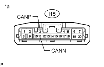 |
Disconnect the connector from the multiplex tilt and telescopic ECU.
Measure the resistance according to the value(s) in the table below.
| Tester Connection | Condition | Specified Condition |
| I15-3 (CANP) - I15-11 (CANN) | Cable disconnected from negative (-) battery terminal | 54 to 69 Ω |
| *a | Front view of wire harness connector (to Multiplex Tilt and Telescopic ECU) |
|
| ||||
| OK | |
|
| 3.CHECK FOR POWER SOURCE CIRCUIT (MULTIPLEX TILT AND TELESCOPIC ECU) |
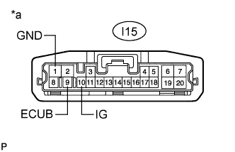 |
Measure the resistance according to the value(s) in the table below.
| Tester Connection | Condition | Specified Condition |
| I15-1 (GND) - Body ground | Cable disconnected from negative (-) battery terminal | Below 1 Ω |
| *a | Front view of wire harness connector (to Multiplex Tilt and Telescopic ECU) |
Reconnect the cable to the negative (-) battery terminal.
Measure the voltage according to the value(s) in the table below.
| Tester Connection | Switch Condition | Specified Condition |
| I15-9 (ECUB) - Body ground | Always | 11 to 14 V |
| I15-10 (IG) - Body ground | Ignition switch ON | 11 to 14 V |
|
| ||||
| OK | |
|
| 4.CHECK DTC OUTPUT |
Reconnect the connector to the multiplex tilt and telescopic ECU.
Connect the intelligent tester to the DLC3.
Turn the ignition switch to ON.
Turn the intelligent tester on.
Clear the DTCs.
Turn the ignition switch off.
Turn the ignition switch to ON and recheck for DTCs.
| Result | Proceed to |
| U1002 is not output | A |
| U1002 is output | B |
|
| ||||
| A | ||
 | ||
| ||
| 5.REPLACE MAIN BODY ECU (MULTIPLEX NETWORK BODY ECU) |
Replace the main body ECU (multiplex network body ECU) (Click here).
| NEXT | |
|
| 6.CHECK DTC OUTPUT |
Connect the intelligent tester to the DLC3.
Turn the ignition switch to ON and recheck for DTCs.
| Result | Proceed to |
| U1002 is not output | A |
| U1002 is output | B |
|
| ||||
| A | ||
| ||
| ||
| 7.CHECK FOR OPEN IN SUB BUS 1 MAIN LINES (MAIN BODY ECU (MULTIPLEX NETWORK BODY ECU)) |
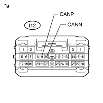 |
Disconnect the main body ECU (multiplex network body ECU) connector.
Measure the resistance according to the value(s) in the table below.
| Tester Connection | Condition | Specified Condition |
| I12-9 (CANP) - I12-10 (CANN) | Cable disconnected from negative (-) battery terminal | 108 to 132 Ω |
| *a | Front view of wire harness connector (to Main Body ECU (Multiplex Network Body ECU)) |
|
| ||||
| OK | ||
| ||
| ||
| 8.CHECK FOR OPEN IN SUB BUS 1 LINES (CAN NO. 3 J/C) |
Reconnect the main body ECU (multiplex network body ECU) connector.
Disconnect the wire harness connectors (I114 and I117) from the CAN No. 3 junction connector.
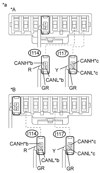 |
Measure the resistance according to the value(s) in the table below.
| Tester Connection | Condition | Specified Condition |
| I114-1 (CANH) - I114-2 (CANL) | Cable disconnected from negative (-) battery terminal | 108 to 132 Ω |
| I117-1 (CANH) - I117-2 (CANL) | Cable disconnected from negative (-) battery terminal | 108 to 132 Ω |
| *A | for TMC Made |
| *B | for TMMR Made |
| *a | Rear view of wire harness connector (to CAN No. 3 Junction Connector) |
| *b | to Main Body ECU (Multiplex Network Body ECU) |
| *c | to CAN No. 4 Junction Connector |
| Result | Proceed to |
| OK | A |
| NG (to Main body ECU (multiplex network body ECU) main bus line) | B |
| NG (to CAN No. 4 junction connector main bus line) | C |
|
| ||||
|
| ||||
| A | ||
| ||
| ||
| 9.CHECK FOR OPEN IN SUB BUS 1 LINES (CAN NO. 4 J/C) |
Reconnect the wire harness connectors (I114 and I117) to the CAN No. 3 junction connector.
Disconnect the wire harness connectors (I120 and I121) from the CAN No. 4 junction connector.
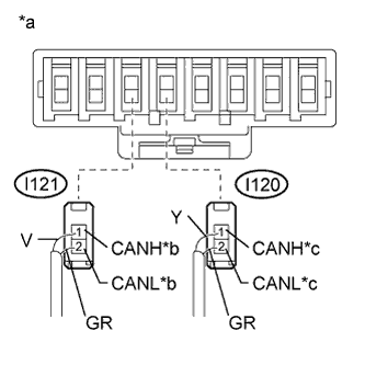 |
Measure the resistance according to the value(s) in the table below.
| Tester Connection | Condition | Specified Condition |
| I120-1 (CANH) - I120-2 (CANL) | Cable disconnected from negative (-) battery terminal | 108 to 132 Ω |
| I121-1 (CANH) - I121-2 (CANL) | Cable disconnected from negative (-) battery terminal | 108 to 132 Ω |
| *a | Rear view of wire harness connector (to CAN No. 4 Junction Connector) |
| *b | to CAN No. 5 Junction Connector |
| *c | to CAN No. 3 Junction Connector |
| Result | Proceed to |
| OK | A |
| NG (to CAN No. 3 junction connector main bus line) | B |
| NG (to CAN No. 5 junction connector main bus line) | C |
|
| ||||
|
| ||||
| A | ||
| ||
| ||
| 10.CHECK FOR OPEN IN SUB BUS 1 LINES (CAN NO. 5 J/C) |
Reconnect the wire harness connectors (I120 and I121) to the CAN No. 4 junction connector.
Disconnect the instrument panel wire connector from the CAN No. 5 junction connector.
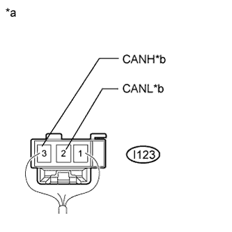 |
Measure the resistance according to the value(s) in the table below.
| Tester Connection | Condition | Specified Condition |
| I123-3 (CANH) - I123-2 (CANL) | Cable disconnected from negative (-) battery terminal | 108 to 132 Ω |
| *a | Rear view of wire harness connector (to CAN No. 5 Junction Connector) |
| *b | to CAN No. 4 Junction Connector |
|
| ||||
| OK | ||
| ||
| ||
| 11.CHECK FOR SHORT IN SUB BUS 1 LINES (MAIN BODY ECU (MULTIPLEX NETWORK BODY ECU)) |
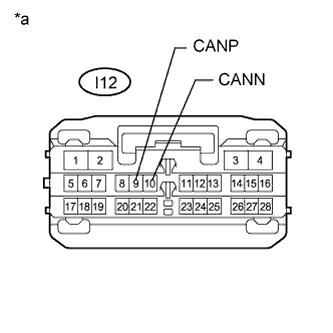 |
Disconnect the main body ECU (multiplex network body ECU) connector.
Measure the resistance according to the value(s) in the table below.
| Tester Connection | Condition | Specified Condition |
| I12-9 (CANP) - I12-10 (CANN) | Cable disconnected from negative (-) battery terminal | 108 to 132 Ω |
| *a | Front view of wire harness connector (to Main Body ECU (Multiplex Network Body ECU)) |
|
| ||||
| OK | ||
| ||
| ||
| 12.CHECK FOR SHORT IN SUB BUS 1 LINES (CAN NO. 3 J/C) |
Reconnect the main body ECU (multiplex network body ECU) connector.
Disconnect the wire harness connectors (I114, I115 and I117) from the CAN No. 3 junction connector.
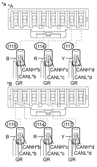 |
Measure the resistance according to the value(s) in the table below.
| Tester Connection | Condition | Specified Condition |
| I114-1 (CANH) - I114-2 (CANL) | Cable disconnected from negative (-) battery terminal | 108 to 132 Ω |
| I115-1 (CANH) - I115-2 (CANL) | Cable disconnected from negative (-) battery terminal | 200 Ω or higher |
| I117-1 (CANH) - I117-2 (CANL) | Cable disconnected from negative (-) battery terminal | 108 to 132 Ω |
| *A | for TMC Made |
| *B | for TMMR Made |
| *a | Rear view of wire harness connector (to CAN No. 3 Junction Connector) |
| *b | to Multiplex Tilt and Telescopic ECU |
| *c | to Main Body ECU (Multiplex Network Body ECU) |
| *d | to CAN No. 4 Junction Connector |
| Result | Proceed to |
| OK | A |
| NG (to Main body ECU (multiplex network body ECU) main bus line) | B |
| NG (to CAN No. 4 junction connector main bus line) | C |
| NG (to Multiplex tilt and telescopic ECU) | D |
|
| ||||
|
| ||||
|
| ||||
| A | ||
| ||
| ||
| 13.CHECK FOR SHORT IN SUB BUS 1 LINES (CAN NO. 4 J/C) |
Disconnect the wire harness connectors (I120 and I121) from the CAN No. 4 junction connector.
|
Measure the resistance according to the value(s) in the table below.
| Tester Connection | Condition | Specified Condition |
| I120-1 (CANH) - I120-2 (CANL) | Cable disconnected from negative (-) battery terminal | 1 MΩ or higher |
| I121-1 (CANH) - I121-2 (CANL) | Cable disconnected from negative (-) battery terminal | 108 to 132 Ω |
| *a | Rear view of wire harness connector (to CAN No. 4 Junction Connector) |
| *b | to CAN No. 5 Junction Connector |
| *c | to CAN No. 3 Junction Connector |
| Result | Proceed to |
| OK | A |
| NG (to CAN No. 3 junction connector main bus line) | B |
| NG (to CAN No. 5 junction connector main bus line) | C |
|
| ||||
|
| ||||
| A | ||
| ||
| ||
| 14.CHECK FOR SHORT IN SUB BUS 1 LINES (CAN NO. 5 J/C) |
Disconnect the wire harness connector from the CAN No. 5 junction connector.
|
Measure the resistance according to the value(s) in the table below.
| Tester Connection | Condition | Specified Condition |
| I123-3 (CANH) - I123-2 (CANL) | Cable disconnected from negative (-) battery terminal | 1 MΩ or higher |
| *a | Rear view of wire harness connector (to CAN No. 5 Junction Connector) |
| *b | to CAN No. 4 Junction Connector |
|
| ||||
| OK | ||
| ||
| ||
| 15.CHECK FOR SHORT IN SUB BUS 1 LINES (MULTIPLEX TILT AND TELESCOPIC ECU) |
Disconnect the connector from the multiplex tilt and telescopic ECU.
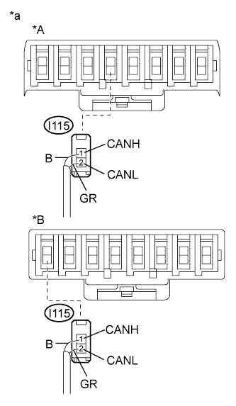 |
Measure the resistance according to the value(s) in the table below.
| Tester Connection | Condition | Specified Condition |
| I115-1 (CANH) - I115-2 (CANL) | Cable disconnected from negative (-) battery terminal | 1 MΩ or higher |
| *A | for TMC Made |
| *B | for TMMR Made |
| *a | Rear view of harness connected (to CAN No. 3 Junction Connector) |
| *b | to Multiplex Tilt and Telescopic ECU |
|
| ||||
| OK | ||
| ||
| ||
| 16.CHECK FOR SHORT IN SUB BUS 1 LINE (CAN NO. 3 J/C) |
Disconnect the wire harness connectors (I114, I115 and I117) from the CAN No. 3 junction connector.
Measure the resistance according to the value(s) in the table below.
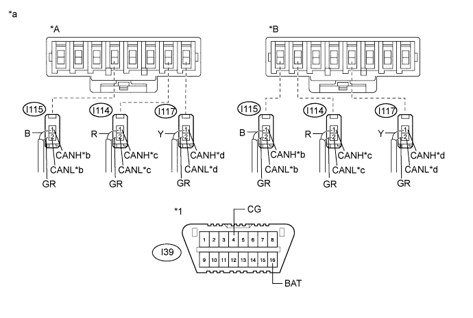
| Tester Connection | Condition | Specified Condition | Purpose | Connected to |
| I114-1 (CANH) - I39-4 (CG) | Cable disconnected from negative (-) battery terminal | 200 Ω or higher | Inspection for CANH ground short | Main body ECU (multiplex network body ECU) |
| I114-2 (CANL) - I39-4 (CG) | Cable disconnected from negative (-) battery terminal | 200 Ω or higher | Inspection for CANL ground short | |
| I117-1 (CANH) - I39-4 (CG) | Cable disconnected from negative (-) battery terminal | 200 Ω or higher | Inspection for CANH ground short | CAN No. 4 junction connector |
| I117-2 (CANL) - I39-4 (CG) | Cable disconnected from negative (-) battery terminal | 200 Ω or higher | Inspection for CANL ground short | |
| I115-1 (CANH) - I39-4 (CG) | Cable disconnected from negative (-) battery terminal | 200 Ω or higher | Inspection for CANH ground short | Multiplex tilt and telescopic ECU |
| I115-2 (CANL) - I39-4 (CG) | Cable disconnected from negative (-) battery terminal | 200 Ω or higher | Inspection for CANL ground short | |
| I114-1 (CANH) - I39-16 (BAT) | Cable disconnected from negative (-) battery terminal | 6 kΩ or higher | Inspection for CANH +B short | Main body ECU (multiplex network body ECU) |
| I114-2 (CANL) - I39-16 (BAT) | Cable disconnected from negative (-) battery terminal | 6 kΩ or higher | Inspection for CANL +B short | |
| I117-1 (CANH) - I39-16 (BAT) | Cable disconnected from negative (-) battery terminal | 6 kΩ or higher | Inspection for CANH +B short | CAN No. 4 junction connector |
| I117-2 (CANL) - I39-16 (BAT) | Cable disconnected from negative (-) battery terminal | 6 kΩ or higher | Inspection for CANL +B short | |
| I115-1 (CANH) - I39-16 (BAT) | Cable disconnected from negative (-) battery terminal | 6 kΩ or higher | Inspection for CANH +B short | Multiplex tilt and telescopic ECU |
| I115-2 (CANL) - I39-16 (BAT) | Cable disconnected from negative (-) battery terminal | 6 kΩ or higher | Inspection for CANL +B short |
| *A | for TMC Made | *B | for TMMR Made |
| *1 | DLC3 | - | - |
| *a | Rear view of wire harness connector (to CAN No. 3 Junction Connector) | *b | to Multiplex Tilt and Telescopic ECU |
| *c | to Main Body ECU (Multiplex Network Body ECU) | *d | to CAN No. 4 Junction Connector |
| Result | Proceed to |
| OK | A |
| NG (to Main body ECU (multiplex network body ECU) main bus line) | B |
| NG (to CAN No. 4 junction connector main bus line) | C |
| NG (to Multiplex tilt and telescopic ECU) | D |
|
| ||||
|
| ||||
|
| ||||
| A | ||
| ||
| ||
| 17.CHECK FOR SHORT IN SUB BUS 1 LINE (MAIN BODY ECU (MULTIPLEX NETWORK BODY ECU)) |
Disconnect the main body ECU (multiplex network body ECU) connector.
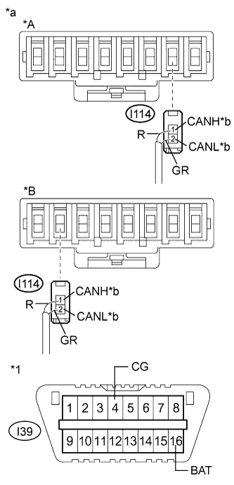 |
Measure the resistance according to the value(s) in the table below.
| Tester Connection | Condition | Specified Condition | Purpose |
| I114-1 (CANH) - I39-4 (CG) | Cable disconnected from negative (-) battery terminal | 200 Ω or higher | Below 200 Ω: CANH ground short |
| I114-2 (CANL) - I39-4 (CG) | Cable disconnected from negative (-) battery terminal | 200 Ω or higher | Below 200 Ω: CANL ground short |
| I114-1 (CANH) - I39-16 (BAT) | Cable disconnected from negative (-) battery terminal | 6 kΩ or higher | Below 6 kΩ: CANH +B short |
| I114-2 (CANL) - I39-16 (BAT) | Cable disconnected from negative (-) battery terminal | 6 kΩ or higher | Below 6 kΩ: CANL +B short |
| *A | for TMC Made |
| *B | for TMMR Made |
| *1 | DLC3 |
| *a | Rear view of wire harness connector (to CAN No. 3 Junction Connector) |
| *b | to Main Body ECU (Multiplex Network Body ECU) |
|
| ||||
| OK | ||
| ||
| ||
| 18.CHECK FOR SHORT IN SUB BUS 1 LINE (CAN NO. 4 J/C) |
Disconnect the wire harness connectors (I120 and I121) from the CAN No. 4 junction connector.
Measure the resistance according to the value(s) in the table below.
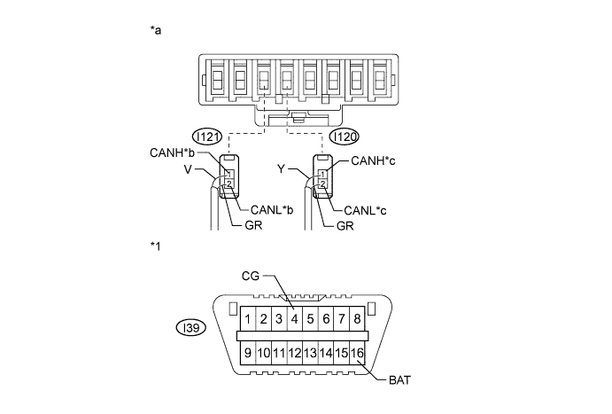
| Tester Connection | Condition | Specified Condition | Purpose | Connected to |
| I120-1 (CANH) - I39-4 (CG) | Cable disconnected from negative (-) battery terminal | 200 Ω or higher | Inspection for CANH ground short | CAN No. 3 junction connector |
| I120-2 (CANL) - I39-4 (CG) | Cable disconnected from negative (-) battery terminal | 200 Ω or higher | Inspection for CANL ground short | |
| I121-1 (CANH) - I39-4 (CG) | Cable disconnected from negative (-) battery terminal | 200 Ω or higher | Inspection for CANH ground short | CAN No. 5 junction connector |
| I121-2 (CANL) - I39-4 (CG) | Cable disconnected from negative (-) battery terminal | 200 Ω or higher | Inspection for CANL ground short | |
| I120-1 (CANH) - I39-16 (BAT) | Cable disconnected from negative (-) battery terminal | 6 kΩ or higher | Inspection for CANH +B short | CAN No. 3 junction connector |
| I120-2 (CANL) - I39-16 (BAT) | Cable disconnected from negative (-) battery terminal | 6 kΩ or higher | Inspection for CANL +B short | |
| I121-1 (CANH) - I39-16 (BAT) | Cable disconnected from negative (-) battery terminal | 6 kΩ or higher | Inspection for CANH +B short | CAN No. 5 junction connector |
| I121-2 (CANL) - I39-16 (BAT) | Cable disconnected from negative (-) battery terminal | 6 kΩ or higher | Inspection for CANL +B short |
| *1 | DLC3 | - | - |
| *a | Rear view of wire harness connector (to CAN No. 4 Junction Connector) | *b | to CAN No. 5 Junction Connector |
| *c | to CAN No. 3 Junction Connector | - | - |
| Result | Proceed to |
| OK | A |
| NG (to CAN No. 3 junction connector main bus line) | B |
| NG (to CAN No. 5 junction connector main bus line) | C |
|
| ||||
|
| ||||
| A | ||
| ||
| ||
| 19.CHECK FOR SHORT IN SUB BUS 1 LINE (CAN NO. 5 J/C) |
Disconnect the wire harness connector from the CAN No. 5 junction connector.
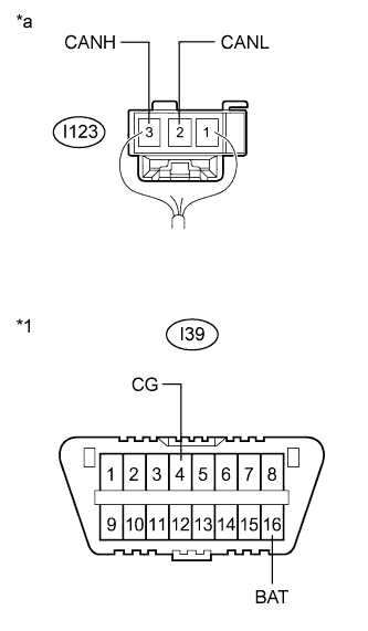 |
Measure the resistance according to the value(s) in the table below.
| Tester Connection | Condition | Specified Condition | Purpose |
| I123-3 (CANH) - I39-4 (CG) | Cable disconnected from negative (-) battery terminal | 200 Ω or higher | Below 200 Ω: CANH ground short |
| I123-2 (CANL) - I39-4 (CG) | Cable disconnected from negative (-) battery terminal | 200 Ω or higher | Below 200 Ω: CANL ground short |
| I123-3 (CANH) - I39-16 (BAT) | Cable disconnected from negative (-) battery terminal | 6 kΩ or higher | Below 6 kΩ: CANH +B short |
| I123-2 (CANL) - I39-16 (BAT) | Cable disconnected from negative (-) battery terminal | 6 kΩ or higher | Below 6 kΩ: CANL +B short |
| *1 | DLC3 |
| *a | Rear view of wire harness connector (to CAN No. 5 Junction Connector) |
|
| ||||
| OK | ||
| ||
| ||
| 20.CHECK FOR SHORT IN SUB BUS 1 LINE (MULTIPLEX TILT AND TELESCOPIC ECU) |
Disconnect the connector from the multiplex tilt and telescopic ECU.
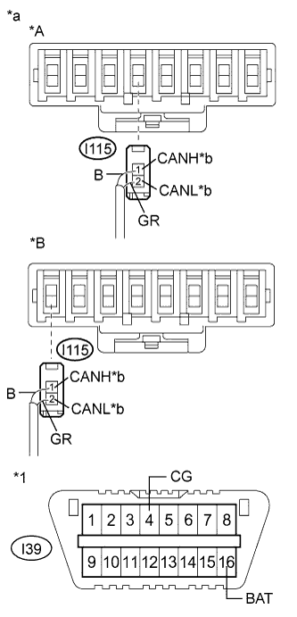 |
Measure the resistance according to the value(s) in the table below.
| Tester Connection | Condition | Specified Condition | Purpose |
| I115-1 (CANH) - I39-4 (CG) | Cable disconnected from negative (-) battery terminal | 200 Ω or higher | Below 200 Ω: CANH ground short |
| I115-2 (CANL) - I39-4 (CG) | Cable disconnected from negative (-) battery terminal | 200 Ω or higher | Below 200 Ω: CANL ground short |
| I115-1 (CANH) - I39-16 (BAT) | Cable disconnected from negative (-) battery terminal | 6 kΩ or higher | Below 6 kΩ: CANH +B short |
| I115-2 (CANL) - I39-16 (BAT) | Cable disconnected from negative (-) battery terminal | 6 kΩ or higher | Below 6 kΩ: CANL +B short |
| *A | for TMC Made |
| *B | for TMMR Made |
| *1 | DLC3 |
| *a | Rear view of wire harness connector (to CAN No. 3 Junction Connector) |
| *b | to Multiplex Tilt and Telescopic ECU |
|
| ||||
| OK | ||
| ||
| ||

