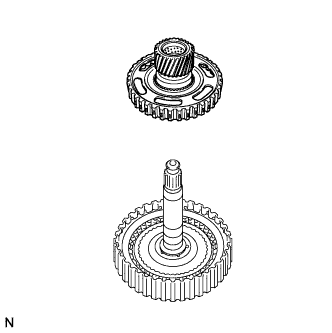
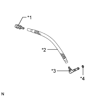
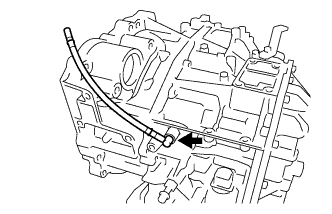
AUTOMATIC TRANSAXLE UNIT > REASSEMBLY |
| 1. BEARING POSITION |
Check bearing position and installation direction.
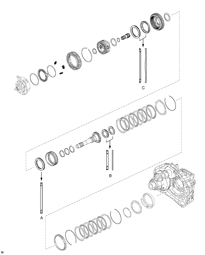
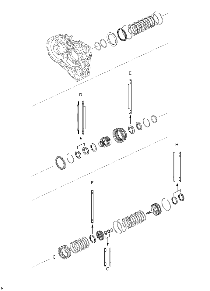
| Mark | Front Race Diameter Inside / Outside mm (in.) | Thrust Bearing Diameter Inside / Outside mm (in.) | Rear Race Diameter Inside / Outside mm (in.) |
| A | - | 57.7 (2.27) / 75.2 (2.96) | - |
| B | - | 29.1 (1.15) / 48.6 (1.91) | 30.7 (1.21) / 48.3 (1.90) |
| C | 65.9 (2.59) / 80.3 (3.16) | 62.6 (2.47) / 82.4 (3.24) | - |
| D | 59.4 (2.34) / 77 (3.03) | 53.1 (2.09) / 79 (3.11) | - |
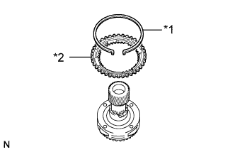
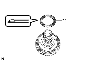
| E | - | 56.1 (2.21) / 80.9 (3.19) | - |
| F | - | 61.2 (2.41) / 79 (3.11) | - |
| G | - | 28 (1.10) / 47.1 (1.85) | 26.1 (1.03) / 44 (1.73) |
| H | 52.2 (2.06) / 70.4 (2.77) | 48.9 (1.93) / 72.0 (2.84) | - |
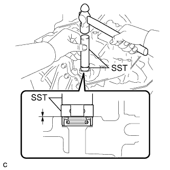
| 2. INSTALL MANUAL VALVE LEVER SHAFT OIL SEAL |
![]() |
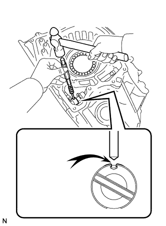
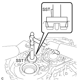
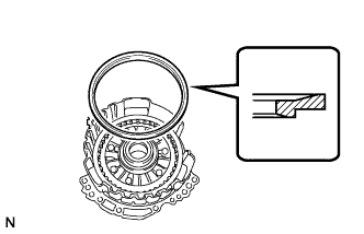
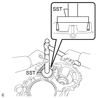
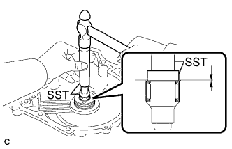
Coat the lip of a new manual valve lever shaft oil seal with MP grease.
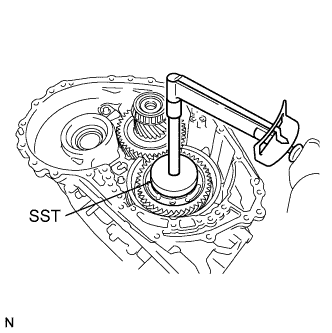
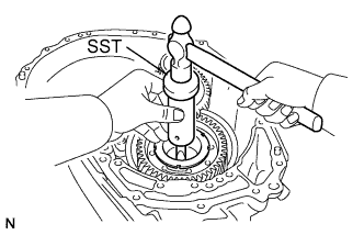
Using SST and a hammer, install the manual valve lever shaft oil seal to the transaxle case sub-assembly.
| 3. INSTALL MANUAL VALVE LEVER SHAFT |
Install a new spacer to the parking lock lever sub-assembly.
Install the parking lock lever sub-assembly to the manual valve lever shaft.
Install a new spacer to the manual valve lever sub-assembly.
Install the manual valve lever sub-assembly to the manual valve lever shaft.
![]() |
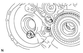
Install the manual valve lever shaft to the transaxle case sub-assembly.
![]() |
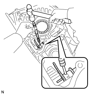
Using a pin punch (3 mm) and hammer, install a new slotted spring pin into the parking lock lever sub-assembly.
![]() |
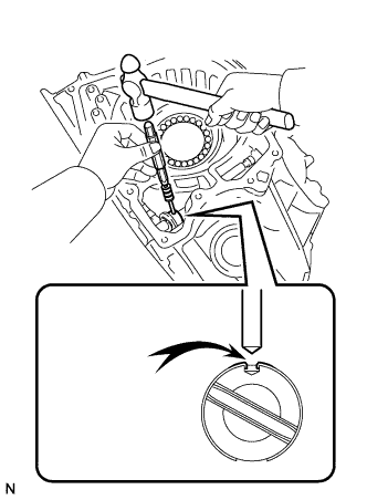
Turn the spacer and the lever shaft to align the smaller hole of the spacer with the staking position mark on the manual valve lever shaft.
Using a pin punch, stake the spacer through the small hole.
Check that the spacer does not turn.
![]() |
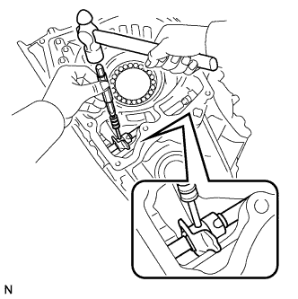
Using a pin punch (3 mm) and hammer, install a new slotted spring pin into the manual valve lever sub-assembly.
![]() |
Turn the spacer and the lever shaft to align the smaller hole of the spacer with the staking position mark on the manual valve lever shaft.
Using a pin punch, stake the spacer through the small hole.
Check that the spacer does not turn.
![]() |
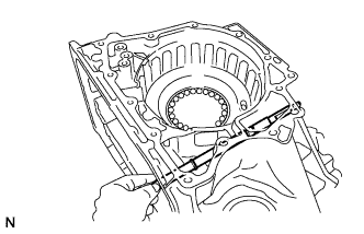
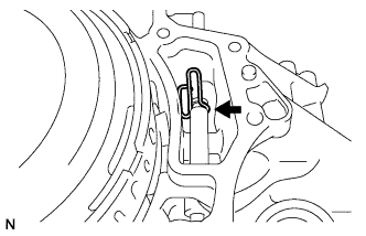
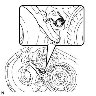
Using needle-nose pliers, install the manual valve shaft retainer spring to the transaxle case sub-assembly.
| 4. INSTALL PARKING LOCK ROD SUB-ASSEMBLY |
![]() |
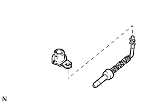
Align the slot with the notches on the parking lock lever sub-assembly and install the parking lock rod sub-assembly.
| 5. INSTALL MANUAL DETENT SPRING SUB-ASSEMBLY |
![]() |
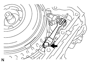
Install the manual detent spring sub-assembly and cover to the transaxle case sub-assembly with the bolt.
| 6. INSTALL NO. 3 BRAKE PISTON |
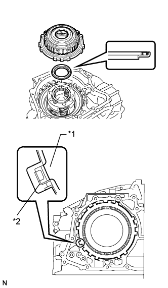
![]() |
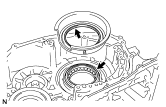
Coat the contact surface of the transaxle case sub-assembly with ATF.
Coat the lip of the No. 3 brake piston with ATF.
![]() |
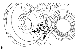
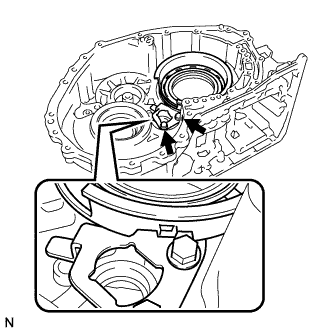
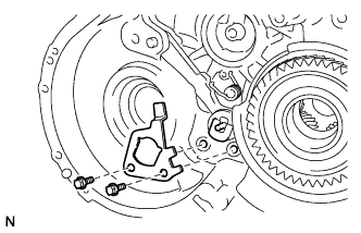
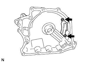
Temporarily install the pawl stopper plate to the transaxle case sub-assembly with the 2 bolts.
![]() |
Press the No. 3 brake piston into the transaxle case sub-assembly.
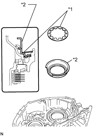
| *1 | Brake Piston Return Spring |
| *2 | No. 3 Brake Piston |
Install the return spring to the transaxle case sub-assembly.
![]() |
Remove the 2 bolts and pawl stopper plate from the transaxle case sub-assembly.
![]() |
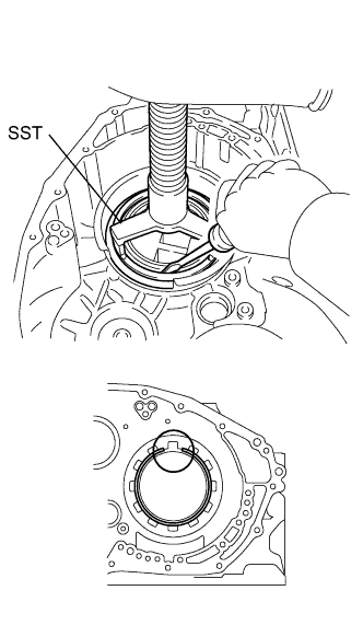
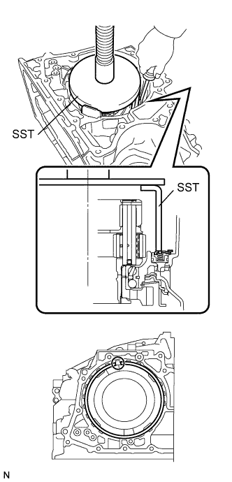
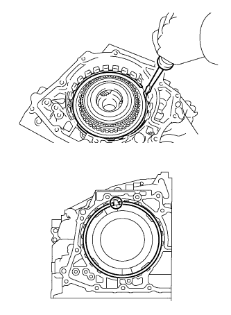
Place SST on the brake piston return spring and compress the brake piston return spring using a press.
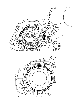
Using a screwdriver, install the snap ring to the transaxle case sub-assembly as shown in the illustration.
| 7. INSTALL COUNTER DRIVE GEAR |
![]() |
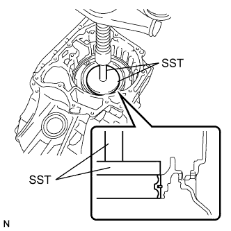
Using SST and a press, install a new counter drive gear bearing and snap ring to the transaxle case sub-assembly.
![]() |
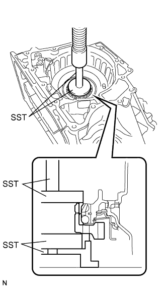
Using SST, install a new bearing inner race (rear side) and counter drive gear to the transaxle case sub-assembly.
| 8. INSTALL FRONT PLANETARY GEAR ASSEMBLY |
![]() |
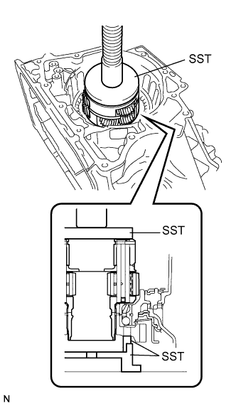
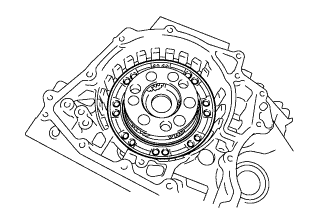
Using SST and a press, press the planetary gear assembly onto the transaxle case sub-assembly.
| 9. INSTALL NO. 2 BRAKE PISTON |
![]() |
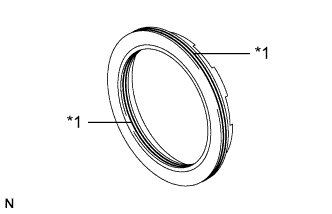
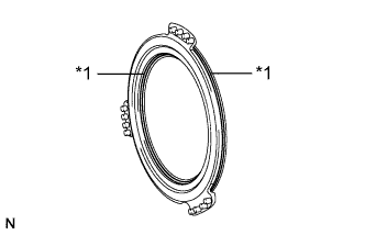
Coat 2 new O-rings with ATF and install them to the No. 2 brake piston.
| *1 | O-ring |
![]() |
Install the No. 2 brake piston to the transaxle case sub-assembly.
| 10. INSTALL 1ST AND REVERSE BRAKE RETURN SPRING SUB-ASSEMBLY |
Install the 1st and reverse brake return spring to the transaxle case sub-assembly.
![]() |
Place SST on the 1st and reverse brake return spring and compress the 1st and reverse brake return spring using a press.
Using a screwdriver, install the snap ring to the transaxle case sub-assembly as shown in the illustration.
| 11. INSTALL NO. 2 BRAKE DISC |
![]() |
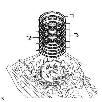
Install the 5 brake discs, 5 brake plates and brake flange to the transaxle case sub-assembly.
| *1 | Brake Flange |
| *2 | Brake Plate |
| *3 | Brake Disc |
![]() |
Using a screwdriver, install the snap ring to the transaxle case sub-assembly.
| 12. INSPECT CLEARANCE OF NO. 2 BRAKE |
![]() |
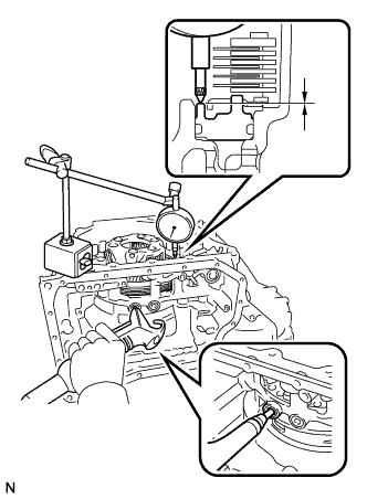
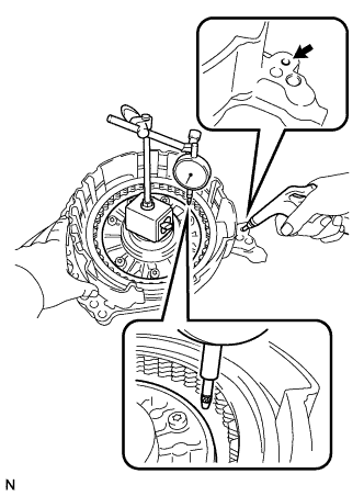
Using a dial indicator, measure the clearance of the No. 2 brake while applying compressed air (200 kPa, 2.0 kgf/cm2, 29 psi).
| Mark | Thickness |
| 40 | 4.0 (0.157) |
| 41 | 4.1 (0.161) |
| 42 | 4.2 (0.165) |
| 43 | 4.3 (0.169) |
| 44 | 4.4 (0.173) |
| 13. INSTALL PLANETARY RING GEAR FLANGE |
![]() |
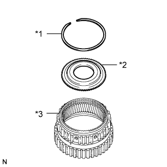
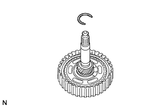
Install the planetary ring gear flange to the planetary ring gear.
| *1 | Snap Ring |
| *2 | Planetary Ring Gear Flange |
| *3 | Planetary Ring Gear |
Using a screwdriver, install the snap ring to the planetary ring gear.
| 14. INSTALL PLANETARY RING GEAR |
![]() |
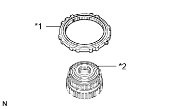
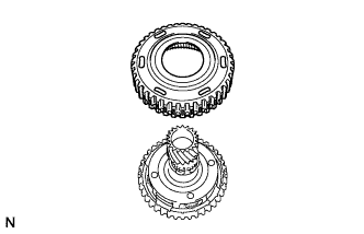
Install the planetary ring gear to the one-way clutch assembly.
| *1 | One-way Clutch Assembly |
| *2 | Planetary Ring Gear |
| 15. INSTALL ONE-WAY CLUTCH ASSEMBLY |
![]() |
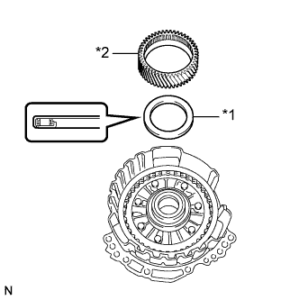
Coat the thrust needle roller bearing with ATF, and install it onto the planetary gear assembly.
| *1 | One-way Clutch Assembly |
| *2 | Thrust Needle Roller Bearing |
| - | Inside | Outside |
| Bearing | 56.1 (2.21) | 80.9 (3.19) |
Install the one-way clutch assembly to the transaxle case sub-assembly.
![]() |
Using a screwdriver, install the snap ring to the transaxle case sub-assembly.
| 16. INSTALL COUNTER DRIVEN GEAR REAR TAPERED ROLLER BEARING OUTER RACE |
![]() |
Using SST and a hammer, install a new counter driven gear rear tapered roller bearing outer race to the transaxle case sub-assembly.
| 17. INSTALL PARKING LOCK PAWL |
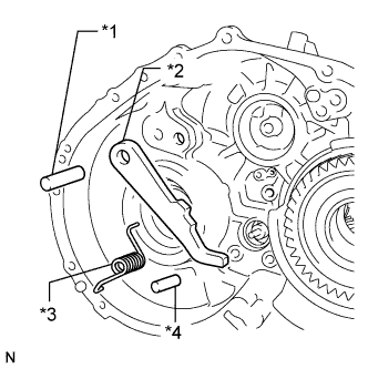
![]() |
Install the parking lock pawl to the transaxle case sub-assembly with the parking lock pawl shaft.
| *1 | Parking Lock Pawl Shaft |
| *2 | Parking Lock Pawl |
| *3 | Spring |
| *4 | Parking Lock Pawl Pin |
Install the parking lock pawl pin to the transaxle case sub-assembly.
![]() |
Install the spring to the parking lock pawl.
| 18. INSTALL PARKING LOCK SLEEVE |
![]() |
Install the parking lock sleeve to the transaxle case sub-assembly.
| 19. INSTALL PAWL STOPPER PLATE |
![]() |
Install the pawl stopper plate to the transaxle case sub-assembly with the 2 bolts.
| 20. INSTALL PAWL SHAFT CLAMP |
![]() |
Install the pawl shaft clamp to the transaxle case sub-assembly with the bolt.
| 21. INSTALL COUNTER DRIVEN GEAR REAR TAPERED ROLLER BEARING |
![]() |
Using SST and a press, install a new counter driven gear rear tapered roller bearing to the counter driven gear sub-assembly.
| 22. INSTALL COUNTER DRIVEN GEAR FRONT TAPERED ROLLER BEARING |
![]() |
Using SST and a press, install a new counter driven gear front tapered roller bearing to the counter driven gear sub-assembly.
| 23. INSTALL COUNTER DRIVEN GEAR |
![]() |
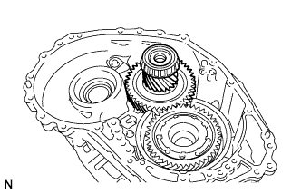
Install the counter driven gear sub-assembly to the transaxle case sub-assembly.
| 24. INSTALL COUNTER DRIVE GEAR NUT |
![]() |
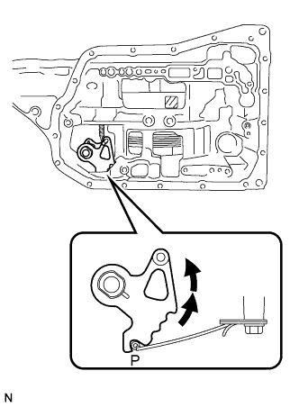
Turn the manual valve lever 2 notches counterclockwise to set it to the P position as shown in the illustration.
![]() |
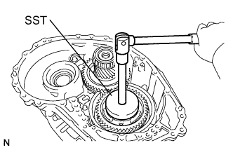
Using SST, install a new counter drive gear nut.
![]() |
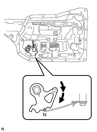
Turn the manual valve lever 2 notches clockwise to set it to the N position as shown in the illustration.
![]() |
Using SST and a torque wrench, measure the turning torque of the bearing while rotating SST at 60 rpm.
![]() |
Using SST and a hammer, stake the planetary gear assembly.
| 25. INSPECT DIFFERENTIAL SIDE GEAR BACKLASH |
![]() |
Hold the differential case in a vise between aluminum plates.
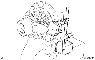
Place a dial indicator at a right angle to one of the side gear teeth.
Hold the pinion gear in the differential case and measure the backlash of the side gear.
| Thickness | Thickness |
| 1.50 mm (0.0591 in.) | 1.75 mm (0.0689 in.) |
| 1.55 mm (0.0610 in.) | 1.80 mm (0.0709 in.) |
| 1.60 mm (0.0630 in.) | 1.85 mm (0.0728 in.) |
| 1.65 mm (0.0650 in.) | 1.90 mm (0.0748 in.) |
| 1.70 mm (0.0669 in.) | - |
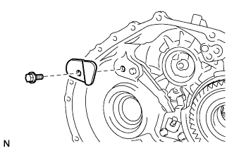
| 26. INSTALL FRONT DIFFERENTIAL CASE |
![]() |
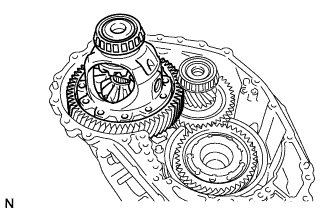
Install the front differential case to the transaxle case sub-assembly.
| 27. INSTALL NO. 1 BRAKE PISTON |
![]() |
Coat 2 new O-rings with ATF and install them to the No. 1 brake piston.
| *1 | O-ring |
![]() |
Install the No. 1 brake piston to the oil pump assembly.
| 28. INSTALL 2ND BRAKE PISTON RETURN SPRING SUB-ASSEMBLY |
![]() |
Install the 3 2nd brake piston return springs to the oil pump assembly.
| 29. INSTALL NO. 1 BRAKE DISC |
![]() |
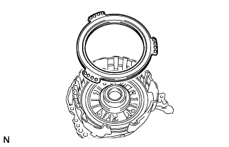
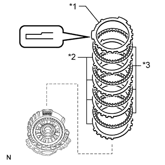
Install the 4 No. 1 brake discs, 4 No. 1 brake plates and No. 1 brake flange to the oil pump assembly.
| *1 | No. 1 Brake Flange |
| *2 | No. 1 Brake Plate |
| *3 | No. 1 Brake Disc |
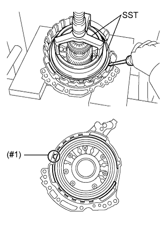
Place SST on the flange and compress the flange using a press.
![]() |
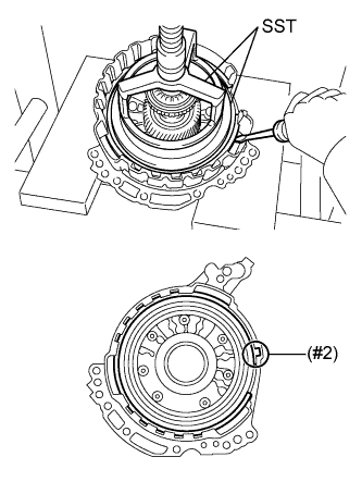
Using a screwdriver, install the snap ring to the oil pump assembly as shown in the illustration (#1).
![]() |
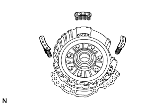
Install the brake snap ring stopper to the oil pump assembly.
![]() |
Using a screwdriver, install the snap ring to the oil pump assembly as shown in the illustration (#2).
![]() |
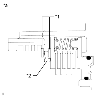
Check that the brake snap ring stopper can be turned by hand.
| *1 | Snap Ring |
| *2 | Brake Snap Ring Stopper |
| *a | Correctly installed |
| 30. INSPECT CLEARANCE OF NO. 1 BRAKE |
![]() |
Using a dial indicator, measure the clearance of the No. 1 brake while applying compressed air (200 kPa, 2.0 kgf/cm2, 29 psi).
| Mark | Thickness |
| 30 | 3.0 (0.118) |
| 31 | 3.1 (0.122) |
| 32 | 3.2 (0.126) |
| 33 | 3.3 (0.130) |
| 34 | 3.4 (0.134) |
| 35 | 3.5 (0.138) |
| 31. INSTALL UNDERDRIVE PLANETARY SUN GEAR |
![]() |
Coat the thrust needle roller bearing with ATF, and install it to the oil pump assembly.
| *1 | Thrust Needle Roller Bearing |
| *2 | Underdrive Planetary Sun Gear |
| - | Inside | Outside |
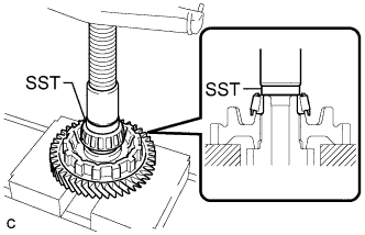
| Bearing | 57.7 (2.27) | 75.2 (2.96) |
Install the underdrive planetary sun gear to the oil pump assembly.
| 32. INSTALL INPUT SHAFT SUB-ASSEMBLY |
![]() |
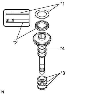
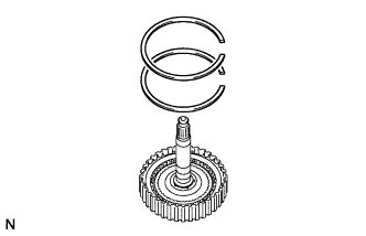
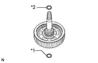
Coat 3 new input shaft oil seal rings with ATF and install them to the input shaft.
| *1 | Thrust Needle Roller Race |
| *2 | Thrust Needle Roller Bearing |
| *3 | Input Shaft Oil Seal Ring |
| *4 | Input Shaft |
Coat the thrust needle roller bearing and thrust needle roller race with ATF, and install them on the oil pump assembly.
| - | Inside | Outside |
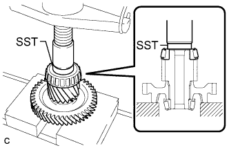
| Bearing | 29.1 (1.15) | 48.6 (1.91) |
| Race | 30.7 (1.21) | 48.3 (1.90) |
![]() |
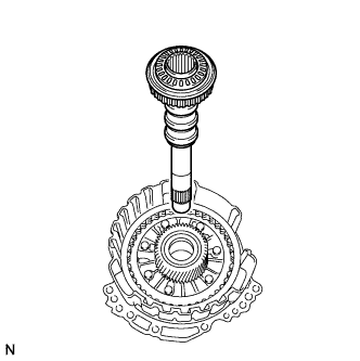
Install the input shaft to the oil pump assembly.
| 33. INSTALL PLANETARY SUN GEAR SUB-ASSEMBLY |
![]() |
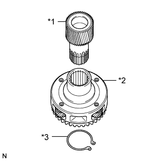
Using a snap ring expander, install the snap ring to the underdrive planetary gear assembly.
| *1 | Planetary Sun Gear Sub-assembly |
| *2 | Underdrive Planetary Gear Assembly |
| *3 | Snap Ring |
Using a snap ring expander, install the planetary sun gear sub-assembly to the underdrive planetary gear assembly with the snap ring expanded.
| 34. INSTALL UNDERDRIVE PLANETARY RING GEAR |
![]() |
Install the underdrive planetary ring gear to the underdrive planetary gear assembly.
| *1 | Snap Ring |
| *2 | Underdrive Planetary Ring Gear |
Using needle-nose pliers, install the snap ring to the underdrive planetary ring gear.
| 35. INSTALL NO. 3 BRAKE HUB |
![]() |
Coat the thrust needle roller bearing with ATF and install it on the underdrive planetary gear assembly.
| *1 | Thrust Needle Roller Bearing |
| - | Inside | Outside |
| Bearing | 62.6 (2.46) | 82.9 (3.26) |
| Race | 65.9 (2.59) | 80.3 (3.16) |
![]() |
Coat the thrust needle roller race with MP grease and install it to the No. 3 brake hub.
| *1 | Thrust Needle Roller Race |
![]() |
Install the No. 3 brake hub to the underdrive planetary gear assembly.
| 36. INSTALL UNDERDRIVE PLANETARY GEAR ASSEMBLY |
![]() |
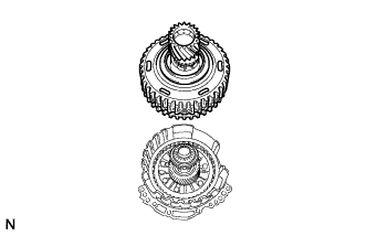
Install the underdrive planetary gear assembly to the oil pump assembly.
| 37. INSTALL NO. 3 BRAKE DISC |
![]() |
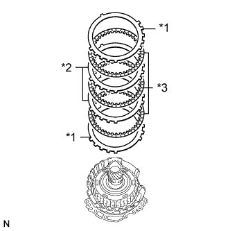
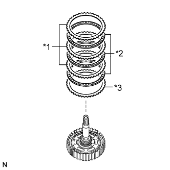
Install the 2 No. 3 brake flanges, 3 No. 3 brake discs and 2 No. 3 brake plates to the oil pump assembly.
| *1 | No. 3 Brake Flange |
| *2 | No. 3 Brake Plate |
| *3 | No. 3 Brake Disc |
![]() |
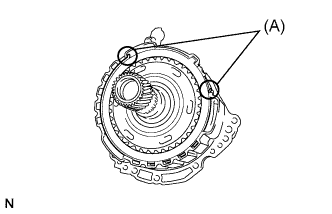
Using a screwdriver, install the snap ring to the oil pump assembly.
| 38. INSPECT CLEARANCE OF NO. 3 BRAKE |
![]() |
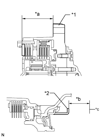
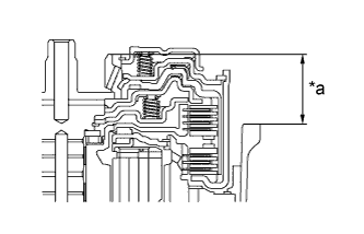
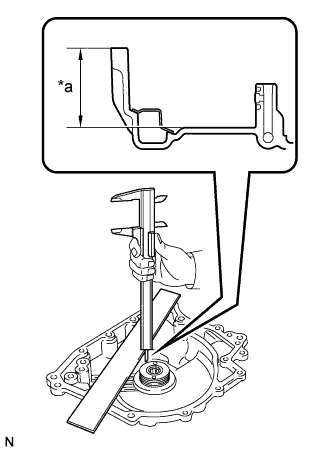
Using a vernier caliper and a straightedge, measure the distance shown in the illustration (Dimension A) while a load of 500 N (51 kgf, 112.4 lbf) is being applied to the flange.
| *1 | Front Oil Pump Assembly |
| *2 | No. 3 Brake Piston |
| *a | Dimension A |
| *b | Dimension B |
| *c | Contact surface of front oil pump assembly |
Using a vernier caliper and a straightedge, measure the distance shown in the illustration (Dimension B).
Calculate the clearance value using the following formula:
Clearance = Dimension B - Dimension A
| Mark | Thickness |
| 38 | 3.80 (0.150) |
| 39 | 3.90 (0.154) |
| 40 | 4.00 (0.157) |
| 41 | 4.10 (0.161) |
| 42 | 4.20 (0.165) |
| 43 | 4.30 (0.169) |
| 39. INSTALL FRONT OIL PUMP ASSEMBLY |
![]() |
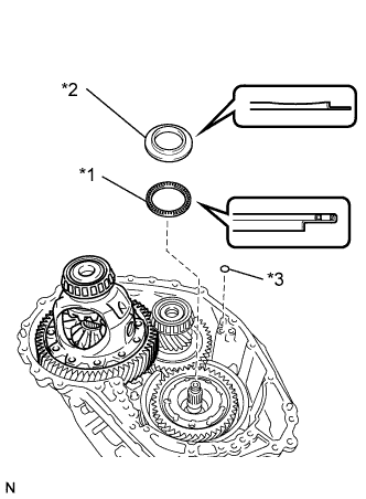
Coat a new O-ring with ATF and install it to the transaxle case sub-assembly.
| *1 | Thrust Needle Roller Bearing |
| *2 | Thrust Needle Roller Race |
| *3 | O-ring |
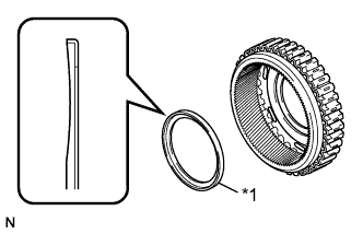
Coat the thrust needle roller bearing and thrust needle roller race with ATF and install them on the underdrive planetary gear assembly.
| - | Inside | Outside |
| Bearing | 53.1 (2.09) | 79 (3.11) |
| Race | 59.4 (2.34) | 77 (3.03) |
![]() |
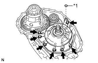
Coat a new O-ring with ATF and install it to the oil pump.
| *1 | O-ring |
Install the oil pump assembly to the transaxle case sub-assembly with the 7 bolts.
| 40. INSTALL FRONT OIL PUMP BODY O-RING |
![]() |
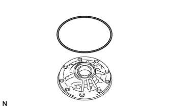
Coat a new O-ring with ATF and install it to the front oil pump body sub-assembly.
| 41. INSTALL DIFFERENTIAL GEAR LUBE APPLY TUBE |
![]() |
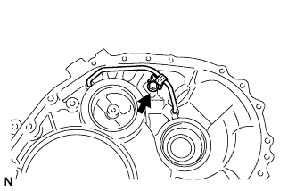
Install the differential gear lube apply tube to the transaxle housing.
Install the apply tube clamp to the differential gear lube apply tube with the bolt.
| 42. INSTALL COUNTER DRIVEN GEAR FRONT TAPERED ROLLER BEARING OUTER RACE |
![]() |
Install the shim to the transaxle housing.
Using SST, install a new counter driven gear front tapered roller bearing outer race to the transaxle housing.
| 43. INSTALL TRANSAXLE HOUSING |
Remove any packing material from the contact surfaces between the transaxle housing and case.
![]() |
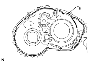
Apply FIPG to the transaxle case sub-assembly.
| *a | FIPG |
![]() |
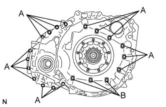
Install the transaxle housing to the transaxle case sub-assembly with the 20 bolts.
| 44. ADJUST COUNTER DRIVEN GEAR PRELOAD |
![]() |
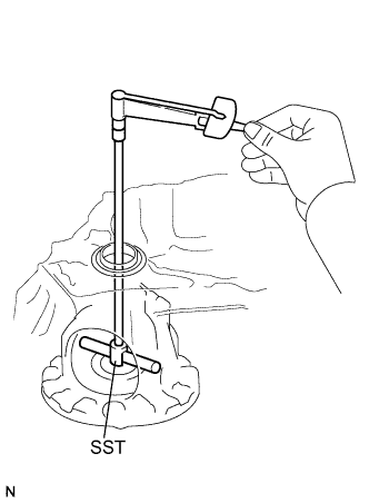
Using SST and a torque wrench, measure the turning torque of the counter driven gear while rotating SST at 10 rpm.
| Thickness | Thickness | Thickness | Thickness |
| 2.000 (0.0787) | 2.275 (0.0896) | 2.525 (0.0994) | 2.775 (0.109) |
| 2.025 (0.0797) | 2.300 (0.0906) | 2.550 (0.100) | 2.800 (0.110) |
| 2.050 (0.0807) | 2.325 (0.0915) | 2.575 (0.101) | 2.825 (0.111) |
| 2.075 (0.0817) | 2.350 (0.0925) | 2.600 (0.102) | 2.850 (0.112) |
| 2.100 (0.0827) | 2.375 (0.0935) | 2.625 (0.103) | 2.875 (0.113) |
| 2.125 (0.0837) | 2.400 (0.0945) | 2.650 (0.104) | 2.900 (0.114) |
| 2.150 (0.0846) | 2.425 (0.0955) | 2.675 (0.105) | 2.925 (0.115) |
| 2.175 (0.0856) | 2.450 (0.0965) | 2.700 (0.106) | 2.950 (0.116) |
| 2.200 (0.0866) | 2.475 (0.0974) | 2.725 (0.107) | 2.975 (0.117) |
| 2.225 (0.0876) | 2.500 (0.0984) | 2.750 (0.108) | 3.000 (0.118) |
| 2.250 (0.0886) | - | - | - |
| 45. INSTALL NO. 1 CLUTCH DISC |
![]() |
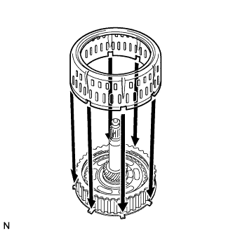
Install the clutch flange, 4 clutch discs and 4 clutch plates to the direct multiple disc clutch assembly.
| *1 | Clutch Flange |
| *2 | Clutch Plate |
| *3 | Clutch Disc |
![]() |
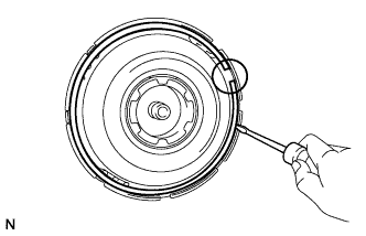
Using a screwdriver, install the 2 snap rings to the direct multiple disc clutch assembly.
| 46. INSPECT CLEARANCE OF NO. 1 CLUTCH DISC |
![]() |
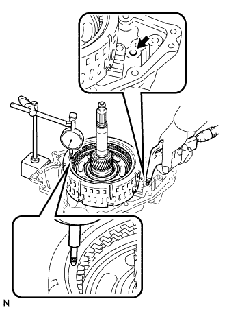
Install the direct multiple disc clutch assembly onto the rear transaxle cover sub-assembly.
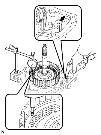
Using a dial indicator, measure the No. 1 clutch pack clearance while applying and releasing compressed air (200 kPa, 2.0 kgf/cm2, 29 psi).
| Mark | Thickness |
| 30 | 3.0 (0.118) |
| 31 | 3.1 (0.122) |
| 32 | 3.2 (0.126) |
| 33 | 3.3 (0.130) |
| 34 | 3.4 (0.134) |
| 35 | 3.5 (0.138) |
| 47. INSTALL REAR PLANETARY SUN GEAR ASSEMBLY |
![]() |
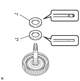
Coat the thrust needle roller bearing and thrust needle roller race with ATF, and install them to the direct multiple disc clutch assembly.
| *1 | Thrust Needle Roller Bearing |
| *2 | Thrust Needle Roller Race |
| - | Inside | Outside |
| Bearing | 28 (1.10) | 47.1 (1.85) |
| Race | 26.1 (1.03) | 44 (1.73) |
![]() |
Install the rear planetary sun gear assembly to the direct multiple disc clutch assembly.
![]() |
Using a snap ring expander, install the snap ring to the direct multiple disc clutch assembly.
| 48. INSTALL NO. 2 CLUTCH DISC |
![]() |
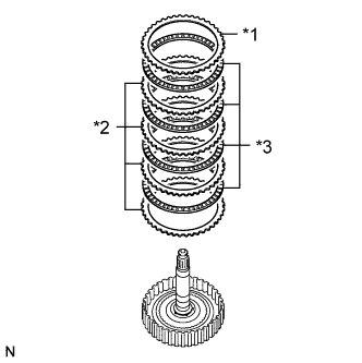
Install the clutch flange, 3 clutch discs and 3 clutch plates to the direct multiple disc clutch assembly.
| *1 | Clutch Plate |
| *2 | Clutch Disc |
| *3 | Clutch Flange |
| 49. INSTALL DIRECT MULTIPLE DISC CLUTCH SNAP RING |
![]() |
Coat a new O-ring with ATF and install it to the direct multiple disc clutch assembly.
| *1 | Intermediate Shaft Oil Seal |
| *2 | O-ring |
Coat a new intermediate shaft oil seal with ATF and install it to the direct multiple disc clutch assembly.
![]() |
Install the No. 2 direct clutch piston to the direct multiple disc clutch assembly.
![]() |
Using a screwdriver, install the snap ring to the direct multiple disc clutch assembly.
| 50. INSPECT CLEARANCE OF NO. 2 CLUTCH DISC |
![]() |
Install the direct multiple disc clutch assembly onto the rear transaxle cover sub-assembly.
Using a dial indicator, measure the No. 2 clutch pack clearance while applying and releasing compressed air (200 kPa, 2.0 kgf/cm2, 29 psi).
| Mark | Thickness |
| 30 | 3.0 (0.118) |
| 31 | 3.1 (0.122) |
| 32 | 3.2 (0.126) |
| 33 | 3.3 (0.130) |
| 34 | 3.4 (0.134) |
| 35 | 3.5 (0.138) |
| 51. INSTALL DIRECT MULTIPLE DISC CLUTCH ASSEMBLY |
![]() |
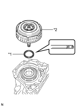
Coat the thrust needle roller bearing with ATF and install it on the transaxle case sub-assembly.
| *1 | Thrust Needle Roller Bearing |
| *2 | Direct Multiple Disc Clutch Assembly |
| - | Inside | Outside |
| Bearing | 61.2 (2.41) | 79 (3.11) |
Install the direct multiple disc clutch assembly to the transaxle case sub-assembly.
Clean the contact surfaces of the transaxle case sub-assembly and rear transaxle cover sub-assembly.
![]() |
As shown in the illustration, place a straightedge on the multiple direct clutch drum and measure the distance between the transaxle case sub-assembly and the straightedge using a vernier caliper (Dimension A).
| *a | Dimension A |
![]() |
Using a vernier caliper and a straightedge, measure the distance shown in the illustration (Dimension B).
| *a | Dimension B |
Calculate the end play value using the following formula:
End play = Dimension B - Dimension A - Thrust needle roller bearing thickness
| 52. INSTALL REAR TRANSAXLE COVER SUB-ASSEMBLY |
![]() |
Using SST and a hammer, install a new needle roller bearing into the rear transaxle cover sub-assembly.
Apply adhesive to the 2 "TORX" screws.
![]() |
Using a "TORX" socket wrench (T30), install the rear transaxle cover plate to the rear transaxle cover sub-assembly with the 2 "TORX" screws.
![]() |
Coat the thrust needle roller bearing and thrust needle roller race with ATF and install them on the transaxle case sub-assembly.
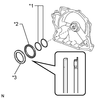
| *1 | Oil Seal Ring |
| *2 | Thrust Needle Roller Bearing |
| *3 | Thrust Needle Roller Race |
| - | Inside | Outside |
| Bearing | 48.9 (1.93) | 72.0 (2.84) |
| Race | 52.2 (2.06) | 70.4 (2.77) |
Coat 2 new oil seal rings with ATF and install them to the rear transaxle cover sub-assembly.
![]() |
Coat 3 new O-rings with ATF and install them to the transaxle case sub-assembly.
![]() |
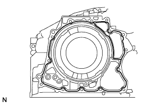
Remove packing material from the contact surfaces between the rear transaxle cover sub-assembly and transaxle case sub-assembly.
![]() |
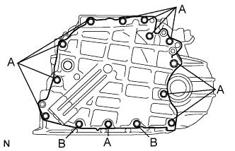
Install the rear transaxle cover sub-assembly to the transaxle case sub-assembly with the 14 bolts.
![]() |
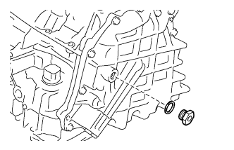
Install a new gasket to the refill plug.
Install the refill plug to the rear transaxle cover sub-assembly.
![]() |
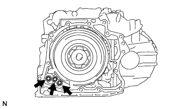
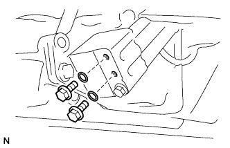
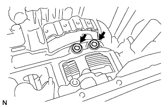
Coat 2 new O-rings with ATF and install them to the 2 No. 1 automatic transaxle case plugs.
Install the 2 No. 1 automatic transaxle case plugs to the rear transaxle cover sub-assembly.
| 53. INSPECT INPUT SHAFT END PLAY |
![]() |
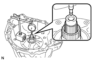
Using a dial indicator, measure the input shaft end play.
| 54. INSTALL TRANSAXLE CASE GASKET |
![]() |
Coat 2 new gaskets with ATF and install them to the transaxle case sub-assembly.
| 55. INSTALL TRANSMISSION VALVE BODY ASSEMBLY |
![]() |
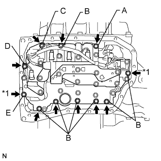
Install the transmission valve body assembly to the transaxle case sub-assembly with the 11 bolts.
| - - | Bolt Length Bolt Length |
| Bolt A | 25 mm (0.984 in.) |
| Bolt B | 30 mm (1.18 in.) |
| Bolt C | 35 mm (1.38 in.) |
| Bolt D | 45 mm (1.77 in.) |
| Bolt E | 55 mm (2.17 in.) |
| 56. INSTALL VALVE BODY OIL STRAINER ASSEMBLY |
![]() |
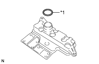
Coat a new O-ring with ATF and install it to the valve body oil strainer assembly.
| *1 | O-ring |
![]() |
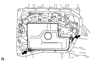
Install the valve body oil strainer assembly to the transmission valve body assembly with the 2 bolts.
| 57. INSTALL AUTOMATIC TRANSAXLE OIL PAN SUB-ASSEMBLY |
![]() |
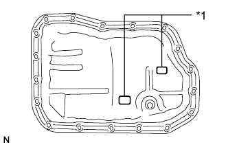
Install the 2 magnets onto the automatic transaxle oil pan sub-assembly as shown in the illustration.
| *1 | Magnet |
Install a new gasket to the automatic transaxle oil pan sub-assembly.
![]() |
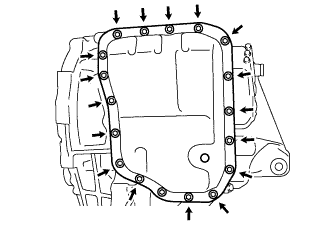
Install the automatic transaxle oil pan sub-assembly to the automatic transaxle assembly with the 17 bolts.
![]() |
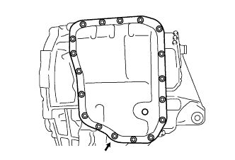
Clean and degrease the bolt and the installation hole in the automatic transaxle assembly.
Apply adhesive to the bolt.
Install the bolt.
![]() |
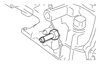
Using a hexagon socket wrench (6 mm), install the No. 1 oil filler tube to the automatic transaxle assembly.
![]() |
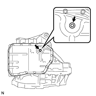
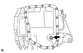
Using a hexagon socket wrench (6 mm), install the overflow plug and a new gasket to the automatic transaxle oil pan sub-assembly.
| 58. INSTALL NO. 1 TRANSAXLE CASE PLUG |
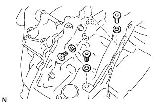
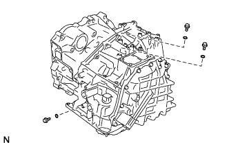
Install 3 new gaskets to the 3 hexagon bolts.
Apply adhesive to the 3 hexagon bolts.
![]() |
Using a hexagon socket wrench (6 mm), install the 3 hexagon bolts to the transaxle housing with the gaskets.
![]() |
Coat 3 new O-rings with ATF and install them to the 3 No. 1 transaxle case plugs.
Install the 3 No. 1 transaxle case plugs to the transaxle case sub-assembly.
| 59. INSTALL OIL COOLER TUBE UNION (INLET OIL COOLER UNION) |
![]() |
Coat a new O-ring with ATF and install it to the oil cooler tube union (inlet oil cooler union).
Install the oil cooler tube union (inlet oil cooler union) to the transaxle case sub-assembly.
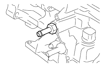
| 60. INSTALL OIL COOLER TUBE UNION (OUTLET OIL COOLER UNION) |
![]() |
Coat a new O-ring with ATF and install it to the oil cooler tube union (outlet oil cooler union).
Install the oil cooler tube union (outlet oil cooler union) to the transaxle case sub-assembly.
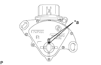
| 61. INSTALL PARK/NEUTRAL POSITION SWITCH ASSEMBLY |
![]() |
Align the protrusions of the park/neutral position switch.
| *a | Protrusion |
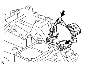
![]() |
Install the park/neutral position switch to the manual valve lever shaft with the 2 bolts.
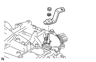
![]() |
Install the transmission control shaft lever to the manual valve lever shaft with the washer and nut.
| 62. INSTALL BREATHER PLUG HOSE |
![]() |
Coat a new O-ring with ATF and install it to the No. 2 breather plug (ATM).
| *1 | No. 1 Breather Plug (ATM) |
| *2 | Breather Plug Hose |
| *3 | No. 2 Breather Plug (ATM) |
| *4 | O-ring |
Install the No. 1 breather plug (ATM) and No. 2 breather plug (ATM) to the breather plug hose.
![]() |
Install the breather plug hose to the transaxle case sub-assembly.