 |
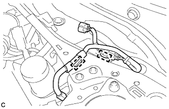
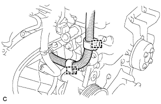
Disengage the 2 clamps and separate the wire harness from the front outer cowl top panel sub-assembly.
CAMSHAFT > REMOVAL |
| 1. REMOVE FRONT WHEEL RH |
| 2. REMOVE FRONT WHEEL OPENING EXTENSION PAD RH |
| 3. REMOVE ENGINE UNDER COVER RH |
| 4. REMOVE FRONT FENDER APRON SEAL RH |
| 5. REMOVE WINDSHIELD WIPER MOTOR AND LINK ASSEMBLY |
| 6. REMOVE FRONT OUTER COWL TOP PANEL SUB-ASSEMBLY |
|
Disengage the 2 clamps and separate the wire harness from the front outer cowl top panel sub-assembly.
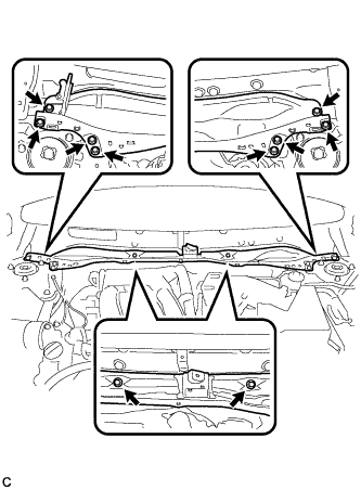 |
Remove the 10 bolts and front outer cowl top panel sub-assembly.
| 7. REMOVE NO. 1 ENGINE COVER SUB-ASSEMBLY |
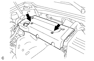 |
Remove the 2 nuts and No. 1 engine cover sub-assembly.
| 8. REMOVE COOL AIR INTAKE DUCT SEAL |
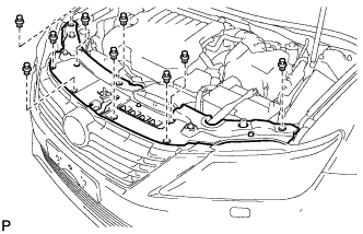 |
Remove the 9 clips and cool air intake duct seal.
| 9. REMOVE INLET AIR CLEANER ASSEMBLY |
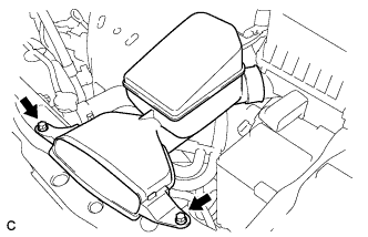 |
Remove the 2 bolts and inlet air cleaner assembly.
| 10. REMOVE AIR CLEANER CAP SUB-ASSEMBLY |
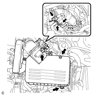 |
Disconnect the vacuum switching valve connector.
Disconnect the 2 vacuum switching valve vacuum hoses.
Disconnect the purge line hose from the 2 clamps.
Disconnect the mass air flow meter connector.
Disconnect the wire harness clamp.
Loosen the 2 bolts and separate the air cleaner cap sub-assembly.
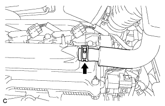 |
Disconnect the ventilation hose from the cylinder head cover sub-assembly.
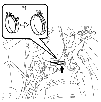 |
Lock the air cleaner hose clamp as shown in the illustration, and disconnect the air cleaner cap sub-assembly from the throttle with motor body assembly.
| *1 | Air Cleaner Hose Clamp |
Remove the air cleaner filter element from the air cleaner case sub-assembly.
| 11. REMOVE AIR CLEANER CASE SUB-ASSEMBLY |
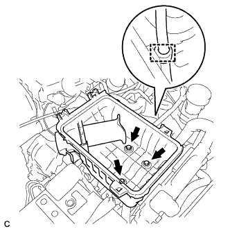 |
Disconnect the wire harness clamp.
Remove the 3 bolts and air cleaner case sub-assembly.
| 12. REMOVE IGNITION COIL ASSEMBLY |
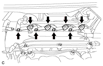 |
Disconnect the 4 ignition coil assembly connectors.
Remove the 4 bolts and 4 ignition coil assemblies.
| 13. REMOVE CYLINDER HEAD COVER SUB-ASSEMBLY |
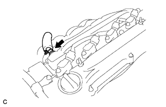 |
Disconnect the No. 2 ventilation hose from the cylinder head cover sub-assembly.
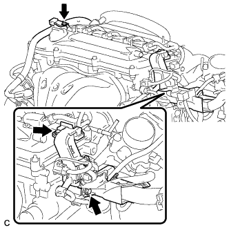 |
Remove the 3 bolts and separate the engine wire.
 |
Disconnect the 2 wire harness clamps.
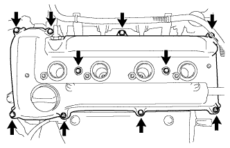 |
Remove the 8 bolts, 2 nuts and cylinder head cover sub-assembly.
Remove the cylinder head cover gasket.
| 14. SET NO. 1 CYLINDER TO TDC/COMPRESSION |
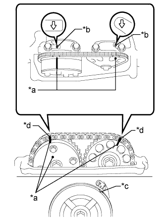 |
Turn the crankshaft pulley until its groove and the timing mark "0" of the timing chain cover sub-assembly are aligned.
| *a | Timing Mark |
| *b | Front Mark |
| *c | Groove |
| *d | Paint Mark |
Check that each timing mark of the camshaft timing gear assembly and camshaft timing sprocket is aligned with each front mark located on the No. 1 and No. 2 bearing caps as shown in the illustration.
If not, turn the crankshaft by 1 revolution (360°) to align the timing marks as above.
Place paint marks on the chain sub-assembly in alignment with the timing marks on the camshaft timing gear assembly and camshaft timing sprocket.
| 15. REMOVE NO. 1 CHAIN TENSIONER ASSEMBLY |
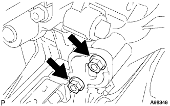 |
Remove the 2 nuts, No. 1 chain tensioner assembly and chain tensioner gasket.
| 16. LOOSEN CAMSHAFT TIMING SPROCKET |
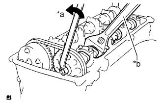 |
While holding the No. 2 camshaft with a wrench, loosen the bolt.
| *a | Loosen |
| *b | Hold |
| 17. REMOVE NO. 2 CAMSHAFT |
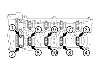 |
Using several steps, uniformly remove the 10 bolts in the order shown in the illustration.
Remove the 5 camshaft bearing caps.
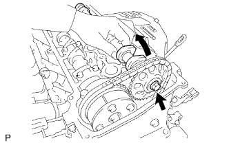 |
While holding the No. 2 camshaft by hand, remove the bolt.
Remove the camshaft timing sprocket and No. 2 camshaft.
| 18. REMOVE CAMSHAFT |
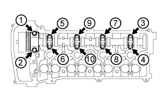 |
Using several steps, uniformly remove the 10 bolts in the order shown in the illustration.
Remove the 5 camshaft bearing caps.
Remove the camshaft and camshaft timing gear assembly.
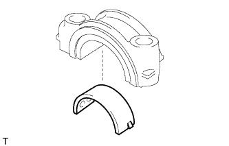 |
Remove the No. 1 camshaft bearing from the No. 1 camshaft bearing cap.
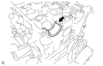 |
Remove the No. 2 camshaft bearing from the cylinder head sub-assembly.
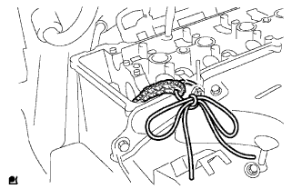 |
Support the chain sub-assembly with a string to prevent it from slipping off the crankshaft timing sprocket as shown in the illustration.
| 19. REMOVE CAMSHAFT TIMING GEAR ASSEMBLY |
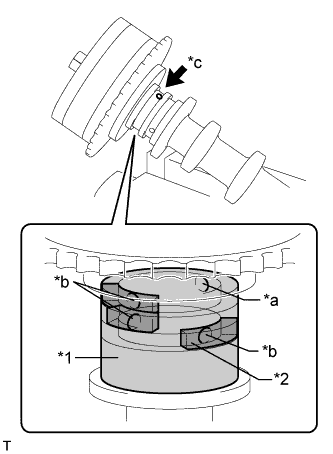 |
Clamp the camshaft in a vise, and make sure that the camshaft timing gear assembly does not rotate.
| *1 | Vinyl Tape |
| *2 | Rubber Piece |
| *a | Open |
| *b | Close |
| *c | Advance Side Path |
Cover all the oil paths with vinyl tape except the advance side path shown in the illustration.
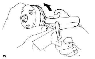 |
Apply air pressure of 150 kPa (1.5 kgf/cm2, 22 psi) to the open oil path, then turn the camshaft timing gear assembly to the advance direction (counterclockwise) by hand.
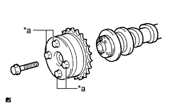 |
Remove the bolt and camshaft timing gear assembly.
| *a | Do Not Remove |