 |
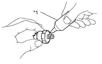
Apply adhesive to 2 or 3 threads of the engine oil pressure switch assembly.
| *1 | Adhesive |
- Adhesive:
- Toyota Genuine Adhesive 1344, Three Bond 1344 or equivalent
ENGINE UNIT > INSTALLATION |
| 1. INSTALL RADIO SETTING CONDENSER |
Install the radio setting condenser with the bolt.
| 2. INSTALL ENGINE COOLANT TEMPERATURE SENSOR |
Install a new gasket to the engine coolant temperature sensor.
Using a 19 mm ball joint lock nut wrench, install the engine coolant temperature sensor.
Connect the engine coolant temperature sensor connector.
| 3. INSTALL ENGINE OIL PRESSURE SWITCH ASSEMBLY |
|
Apply adhesive to 2 or 3 threads of the engine oil pressure switch assembly.
| *1 | Adhesive |
Using a 24 mm deep socket wrench, install the engine oil pressure switch assembly.
Connect the engine oil pressure switch connector.
| 4. INSTALL KNOCK CONTROL SENSOR |
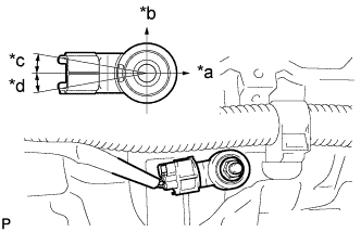 |
Install the knock control sensor with the bolt so that the knock control sensor is positioned as shown in the illustration.
| *a | Front of Engine |
| *b | Up |
| *c | 10° |
| *d | 10° |
Connect the knock control sensor connector.
| 5. INSTALL IGNITION COIL ASSEMBLY |
Install the 4 ignition coil assemblies with the 4 bolts.
Connect the 4 ignition coil assembly connectors.
| 6. INSTALL NO. 1 WATER BY-PASS PIPE |
Install a new water by-pass pipe gasket and the No. 1 water by-pass pipe with the bolt and 2 nuts.
| 7. INSTALL ENGINE OIL LEVEL DIPSTICK GUIDE |
Install a new engine oil level dipstick guide O-ring and the engine oil level dipstick guide with the bolt.
| 8. INSTALL ENGINE OIL LEVEL DIPSTICK |
Install the engine oil level dipstick.
| 9. INSTALL THERMOSTAT |
Install a new gasket to the thermostat.
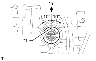 |
Install the thermostat with the jiggle valve facing upward.
| *1 | Jiggle Valve |
| *a | Upward |
| 10. INSTALL WATER INLET |
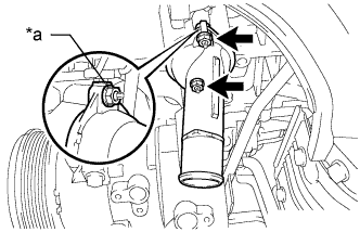 |
Install the water inlet with the mark upward.
| *a | Mark |
Install the water inlet with the 2 nuts.
| 11. INSTALL EXHAUST MANIFOLD CONVERTER SUB-ASSEMBLY |
Set a new gasket to the cylinder head sub-assembly.
Temporarily install the exhaust manifold converter sub-assembly with the 5 nuts.
Temporarily install the No. 2 manifold stay and manifold stay with the 2 bolts and 2 nuts.
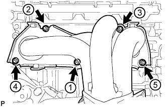 |
Using a 12 mm deep socket wrench, install the exhaust manifold converter sub-assembly and 5 nuts in the order shown in the illustration.
Connect the air fuel ratio sensor connector.
| 12. INSTALL NO. 2 MANIFOLD STAY |
Install the No. 2 manifold stay with the bolt and nut.
| 13. INSTALL MANIFOLD STAY |
Install the manifold stay with the bolt and nut.
| 14. INSTALL NO. 1 EXHAUST MANIFOLD HEAT INSULATOR |
Install the No. 1 exhaust manifold heat insulator with the 4 bolts.
| 15. INSTALL NO. 1 INTAKE MANIFOLD INSULATOR |
Install the No. 1 intake manifold insulator to the cylinder block.
| 16. INSTALL INTAKE MANIFOLD |
Install the vacuum hose clamp with the bolt.
Install a new No. 1 intake manifold to head gasket to the intake manifold.
Set the intake manifold on the engine assembly.
Using an E7 "TORX" wrench, install the 2 stud bolts.
Temporarily install the intake manifold with the 5 bolts and 2 nuts.
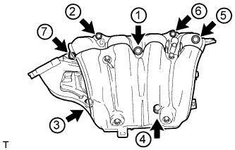 |
Tighten the 5 bolts and 2 nuts in the order shown in the illustration.
Connect the oxygen sensor connector and 2 wire harness clamps.
| 17. CONNECT UNION TO VACUUM TUBE HOSE |
Connect the union to vacuum tube hose to the intake manifold.
| 18. CONNECT NO. 2 VENTILATION HOSE |
Connect the No. 2 ventilation hose to the intake manifold.
| 19. INSTALL FUEL DELIVERY PIPE |
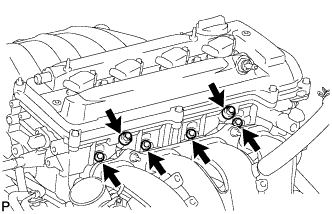 |
Install 4 new injector vibration insulators to the cylinder head.
Install the 2 fuel delivery spacers onto the cylinder head.
Install the fuel delivery pipe sub-assembly with the 4 fuel injector assemblies and install the 2 bolts.
Connect the 4 fuel injector connectors.
Install the 2 wire harness clamps.
| 20. INSTALL THROTTLE WITH MOTOR BODY ASSEMBLY |
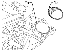 |
Install a new gasket to the intake manifold.
| *a | Groove |
| *b | Protrusion |
Temporarily install the throttle with motor body assembly and fuel tube bracket with the 4 bolts.
Connect the 2 water by-pass hoses.
Connect the purge line hose.
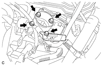 |
Install the fuel tube bracket and the throttle with motor body assembly with the 4 bolts.
Connect the throttle with motor body assembly connector to the throttle with motor body assembly.
Connect the wire harness clamp to the fuel tube bracket.
Install the fuel tube to the fuel tube bracket.
| 21. INSTALL IDLER PULLEY BRACKET |
Install the idler pulley bracket with the 2 bolts.
| 22. INSTALL ENGINE HANGERS |
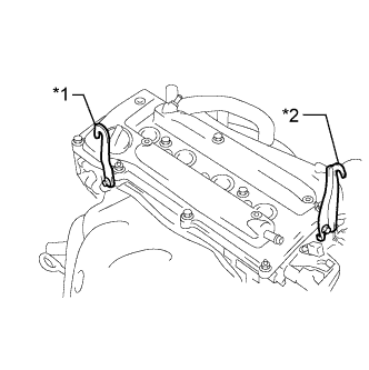 |
Install the 2 engine hangers with the 2 bolts.
| *1 | No. 1 Engine Hanger |
| *2 | No. 2 Engine Hanger |
| Part Name | Part No. |
| No. 1 engine hanger | 12281-28010 |
| No. 2 engine hanger | 12282-28010 |
| Bolt | 91552-B1020 |