 |
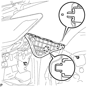
Engage the 2 claws and install the front bumper side retainer LH.
FRONT BUMPER > REASSEMBLY |
| 1. INSTALL FRONT BUMPER SIDE RETAINER LH |
|
Engage the 2 claws and install the front bumper side retainer LH.
Install the bolt and screw.
| 2. INSTALL FRONT BUMPER SIDE RETAINER RH |
| 3. INSTALL FRONT BUMPER REINFORCEMENT SUB-ASSEMBLY |
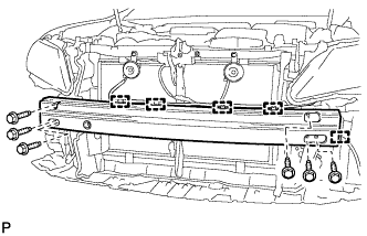 |
Install the front bumper reinforcement sub-assembly with the 6 bolts.
Engage the 5 clamps.
| 4. INSTALL FRONT BUMPER ENERGY ABSORBER |
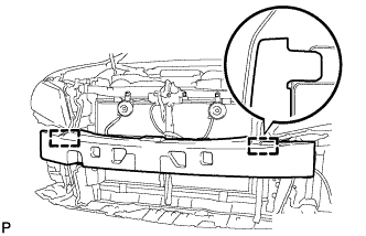 |
Engage the 2 guides to install the front bumper energy absorber.
| 5. INSTALL LOWER FRONT BUMPER COVER |
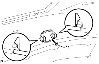 |
Engage the hook.
| *1 | Hook |
Engage the 2 claws to install the lower front bumper cover.
| 6. INSTALL FRONT BUMPER EXTENSION MOUNTING BRACKET |
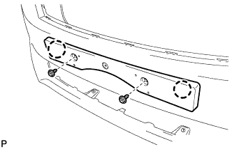 |
Engage the 2 claws.
Install the front bumper extension mounting bracket with the 2 screws.
| 7. INSTALL FRONT BUMPER HOLE COVER LH |
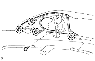 |
Engage the 4 claws.
Install the front bumper hole cover LH with the screw.
| 8. INSTALL FRONT BUMPER HOLE COVER RH |
| 9. INSTALL NO. 1 LOWER RADIATOR GRILLE |
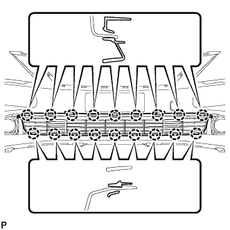 |
Engage the 18 claws to install the No. 1 lower radiator grille.
| 10. INSTALL RADIATOR GRILLE EMBLEM ASSEMBLY |
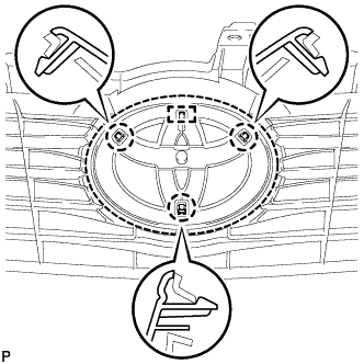 |
Engage the guide and 3 claws to install the radiator grille emblem assembly.
| 11. INSTALL RADIATOR GRILLE SUB-ASSEMBLY |
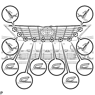 |
Engage the 10 claws to install the radiator grille sub-assembly.
| 12. INSTALL FRONT FENDER LINER RETAINER |
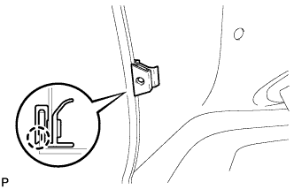 |
Engage the claw and install the front fender liner retainer.
| 13. INSTALL FOG LIGHT ASSEMBLY LH (w/ Fog Light) |
Engage the 2 guides to temporarily install the fog light assembly.
Install the fog light assembly with the screw.
for TMC Made:
Connect the connector.
| 14. INSTALL FOG LIGHT ASSEMBLY RH (w/ Fog Light) |
| 15. INSTALL NO. 1 ULTRASONIC SENSOR RETAINER (w/ TOYOTA Parking Assist-sensor System) |
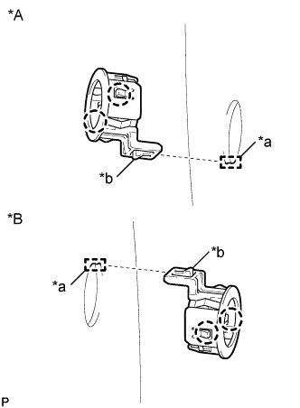 |
Engage the 2 claws to install the No. 1 ultrasonic sensor retainer to the front bumper assembly.
| *A | LH Side |
| *B | RH Side |
| *a | Keyhole |
| *b | Snap |
| 16. INSTALL NO. 1 ULTRASONIC SENSOR (w/ TOYOTA Parking Assist-sensor System) |
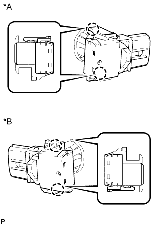 |
Engage the 2 claws to install the No. 1 ultrasonic sensor to the No. 1 ultrasonic sensor retainer.
| *A | LH Side |
| *B | RH Side |
for TMC Made:
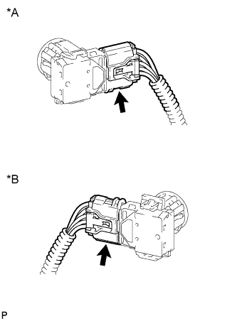 |
Connect the connector.
| *A | LH Side |
| *B | RH Side |
| 17. INSTALL NO. 4 ENGINE ROOM WIRE (for TMC Made) |
w/ Fog Light without TOYOTA Parking Assist-sensor System:
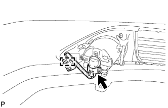 |
Engage the clamp.
Connect the connector to install the No. 4 engine room wire.
w/ Fog Light and TOYOTA Parking Assist-sensor System:
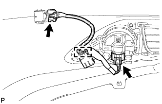 |
Engage the clamp.
Connect the 2 connectors to install the No. 4 engine room wire.
| 18. INSTALL HEADLIGHT CLEANER HOSE (w/ Headlight Cleaner System) |
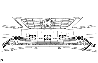 |
Engage the 5 clamps to install the headlight cleaner hose.
| 19. INSTALL HEADLIGHT WASHER ACTUATOR SUB-ASSEMBLY LH (w/ Headlight Cleaner System) |
Engage the guide to the front bumper assembly, then push the tab (A) and engage the claw as shown in the illustration.
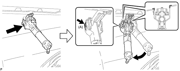
Install the bolt.
Connect the headlight cleaner hose and engage the clip.
| 20. INSTALL HEADLIGHT WASHER ACTUATOR SUB-ASSEMBLY RH (w/ Headlight Cleaner System) |
| 21. INSTALL HEADLIGHT WASHER NOZZLE SUB-ASSEMBLY LH (w/ Headlight Cleaner System) |
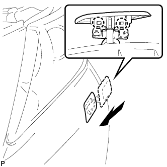 |
Engage the 2 claws to install the headlight washer nozzle sub-assembly.
| 22. INSTALL HEADLIGHT WASHER NOZZLE SUB-ASSEMBLY RH (w/ Headlight Cleaner System) |