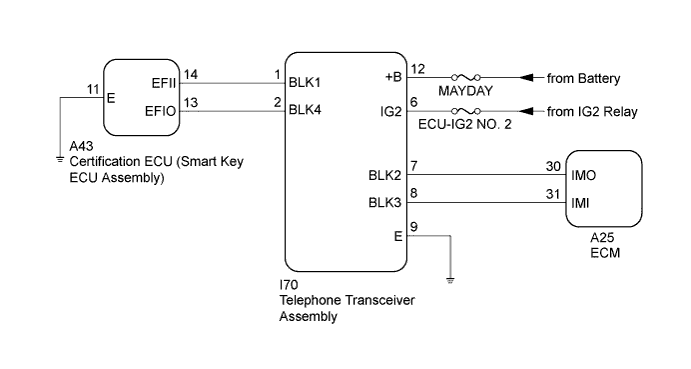
BLOCKING SYSTEM > Engine does not Start |
| 1.CHECK BLOCKING SYSTEM (SETTING) |
Check the blocking system setting.
| Result | Proceed to |
| Blocking system is unset. | A |
| Blocking system is set. | B |
|
| ||||
| A | |
 |
| 2.CHECK HARNESS AND CONNECTOR (TELEPHONE TRANSCEIVER ASSEMBLY - CERTIFICATION ECU (SMART KEY ECU ASSEMBLY)) |
Disconnect the I70 telephone transceiver assembly connector.
Disconnect the A43 certification ECU (smart key ECU assembly) connector.
Measure the resistance according to the value(s) in the table below.
| Tester Connection | Condition | Specified Condition |
| I70-1 (BLK1) - A43-14 (EFII) | Always | 10 kΩ or higher |
| I70-2 (BLK4) - A43-13 (EFIO) | Always | 10 kΩ or higher |
|
| ||||
| OK | |
|
| 3.CHECK CERTIFICATION ECU (SMART KEY ECU ASSEMBLY) (OUTPUT) |
Reconnect the I70 telephone transceiver assembly connector.
Reconnect the A43 certification ECU (smart key ECU assembly) connector.
Using an oscilloscope, check the waveform.
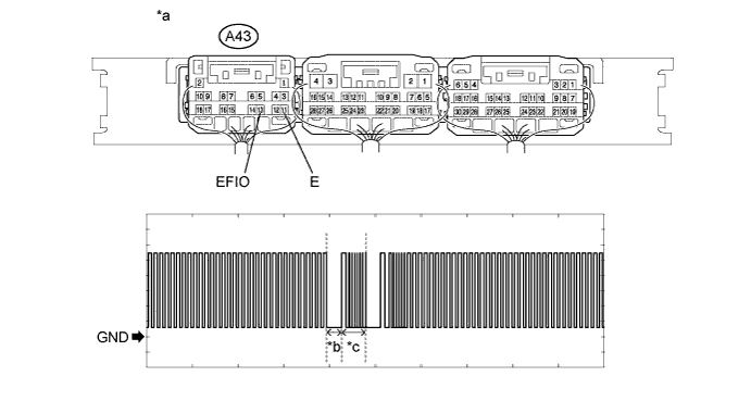
| *a | Component with harness connected (Certification ECU (Smart Key ECU Assembly)) | *b | Approximately 160 ms |
| *c | Approximately 270 ms | - | - |
| Item | Content |
| Tester Connection | A43-13 (EFIO) - A43-11 (E) |
| Tool Setting | 2 V/DIV., 500 ms./DIV. |
| Condition | Within 3 seconds of engine start or within 3 seconds of engine switch turned on (IG) after battery cable disconnected and reconnected |
| Result | Proceed to |
| NG (stuck high) | A |
| NG (stuck low) | B |
| OK | C |
|
| ||||
|
| ||||
| A | |
|
| 4.REPLACE CERTIFICATION ECU (SMART KEY ECU ASSEMBLY) |
Temporarily replace the certification ECU (smart key ECU assembly) with a new one.
| NEXT | |
|
| 5.PERFORM REGISTRATION |
Perform the registration.
| NEXT | |
|
| 6.CHECK WHETHER ENGINE STARTS |
Check that the engine starts normally.
|
| ||||
| OK | ||
 | ||
| ||
| 7.REGISTER ECU COMMUNICATION ID |
Register the ECU communication ID between the ECM and certification ECU (smart key ECU assembly).
| NEXT | |
|
| 8.CHECK WHETHER ENGINE STARTS |
Check that the engine starts normally.
|
| ||||
| OK | ||
| ||
| ||

