WHEN REMOVING,INSTALLING,REPAIRING OR REPLACING PARTS > WHEEL ALIGNMENT STANDARD |
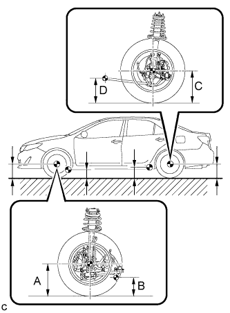
| MEASURE VEHICLE HEIGHT |
|
Bounce the vehicle up and down at the corners to stabilize the suspension.
Measure the vehicle height.
| Engine | Tire Size | Front A - B | Rear C - D |
| 2AR-FE | 205/65R16 | 124 mm (4.88 in.) | 52 mm (2.05 in.) |
| 215/55R17 | 123 mm (4.84 in.)*1 113 mm (4.45 in.)*1, *4 | 51 mm (2.00 in.)*1 41 mm (1.61 in.)*1, *4 | |
| 126 mm (4.96 in.)*2 116 mm (4.57 in.)*2, *4 | 54 mm (2.13 in.)*2 44 mm (1.73 in.)*2, *4 | ||
| 125 mm (4.92 in.)*3 | 52 mm (2.05 in.)*3 | ||
| 225/45R18 | 124 mm (4.88 in.) | 51 mm (2.00 in.) | |
| 2GR-FE | 215/55R17 | 128 mm (5.04 in.) 118 mm (4.65 in.)*4 | 57 mm (2.24 in.) 47 mm (1.853 in.)*4 |
| 225/45R18 | 124 mm (4.88 in.) | 54 mm (2.13 in.) |
| INSPECT CAMBER, CASTER AND STEERING AXIS INCLINATION |
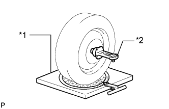 |
Install a camber-caster-kingpin gauge and place the front wheels on the center of a turning radius gauge.
| *1 | Turning Radius Gauge |
| *2 | Camber-caster-kingpin Gauge |
Inspect the camber, caster and steering axis inclination.
| Camber Inclination | Right-left Difference |
| -0°40' +/- 0°45' (-0.67° +/- 0.75°) -0°40' +/- 0°45' (-0.67° +/- 0.75°)* | 0°45' (0.75°) or less |
| Caster Inclination | Right-left Difference |
| 3°05' +/- 0°45' (3.08° +/- 0.75°) 3°00' +/- 0°45' (3.00° +/- 0.75°)* | 0°45' (0.75°) or less |
| Engine | Tire Size | Steering Axis Inclination |
| 2AR-FE | 205/65R16 | 12°15' (12.25°) |
| 215/55R17 | 12°15' (12.25°)*1 12°00' (12.00°)*1, *4 | |
| 12°20' (12.67°)*2 12°05' (12.08°)*2, *4 | ||
| 12°15' (12.25°)*3 | ||
| 225/45R18 | 12°15' (12.25°) | |
| 2GR-FE | 215/55R17 | 12°20' (12.67°) 12°05' (12.08°)*4 |
| 225/45R18 | 12°15' (12.25°) |
| INSPECT TOE-IN (FRONT) |
Bounce the vehicle up and down at the corners to stabilize the suspension.
Release the parking brake and move the shift lever to N.
Push the vehicle straight ahead approximately 5 m (16.4 ft.). (Step C)
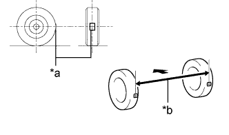 |
Put tread center marks on the rearmost points of the front wheels and measure the distance between the marks (dimension B).
| *a | Tread Center Mark |
| *b | Dimension B |
 | Front of the Vehicle |
Slowly push the vehicle straight ahead to cause the front wheels to rotate 180°. Use the front tire valve as a reference point.
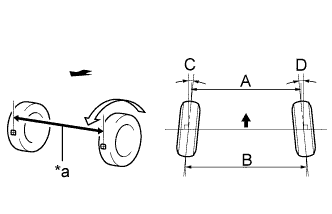 |
Measure the distance between the tread center marks on the front side of the wheels (dimension A).
| *a | Dimension A |
| Front of the Vehicle |
| Specified Condition |
| C + D: 0°00' +/- 0°10' (0.00° +/- 0.17°) |
| B - A: 0 +/- 2.0 mm (0 +/- 0.0787in.) |
| INSPECT WHEEL ANGLE |
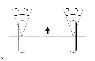 |
Put tread center marks on the rearmost points of a turning radius gauge.
| *a | Inside |
| *b | Outside |
| Front of the Vehicle |
Turn the steering wheel fully to the left and right and measure the turning angle.
| Engine | Tire Size | Inside Wheel | Outside Wheel Reference |
| 2AR-FE | 205/65R16 | 37°15' +/- 2° (37.25° +/- 2°) | 32°50' +/- 2°(32.83° +/- 2°) |
| 215/55R17 | 37°17' +/- 2° (37.28° +/- 2°)*1 37°34' +/- 2° (37.57° +/- 2°)*1, *4 | 32°51' +/- 2°(32.85° +/- 2°)*1 33°02' +/- 2°(33.03° +/- 2°)*1, *4 | |
| 37°11' +/- 2° (37.18° +/- 2°)*2 37°29' +/- 2° (37.48° +/- 2°)*2, *4 | 32°48' +/- 2°(32.80° +/- 2°)*2 32°59' +/- 2°(32.98° +/- 2°)*2, *4 | ||
| 37°14' +/- 2° (37.23° +/- 2°)*3 | 32°49' +/- 2°(32.82° +/- 2°)*3 | ||
| 225/45R18 | 37°16' +/- 2° (37.27° +/- 2°) | 32°50' +/- 2°(32.83° +/- 2°) | |
| 2GR-FE | 215/55R17 | 37°09' +/- 2° (37.15° +/- 2°) 37°26' +/- 2° (37.43° +/- 2°)*4 | 32°46' +/- 2°(32.77° +/- 2°) 32°58' +/- 2°(32.97° +/- 2°)*4 |
| 225/45R18 | 37°17' +/- 2° (37.28° +/- 2°) | 32°51' +/- 2°(32.85° +/- 2°) |
| INSPECT CAMBER (REAR) |
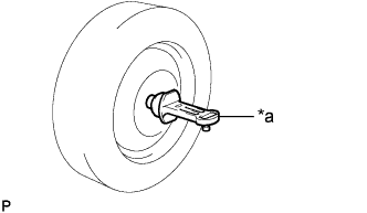 |
Install a camber-caster-kingpin gauge.
| *1 | Camber-caster-kingpin Gauge |
Inspect the camber.
| Engine | Tire Size | Camber Inclination | Right-left Difference |
| 2AR-FE | 205/65R16 | -1°12' +/- 45' (-1.20° +/- 0.75°) | 45' (0.75°) or less |
| 215/55R17 | -1°11' +/- 45' (-1.18° +/- 0.75°)*1 -1°02' +/- 45' (-1.03° +/- 0.75°)*1, *4 | ||
| -1°14' +/- 45' (-1.23° +/- 0.75°)*2 -1°05' +/- 45' (-1.08° +/- 0.75°)*2, *4 | |||
| -1°12' +/- 45' (-1.20° +/- 0.75°)*3 | |||
| 225/45R18 | -1°12' +/- 45' (-1.20° +/- 0.75°) | ||
| 2GR-FE | 215/55R17 | -1°16' +/- 45' (-1.20° +/- 0.75°) -1°08' +/- 45' (-1.13° +/- 0.75°)*4 | |
| 225/45R18 | -1°14' +/- 45' (-1.23° +/- 0.75°) |
| INSPECT TOE-IN (REAR) |
Bounce the vehicle up and down at the corners to stabilize the suspension.
Release the parking brake and move the shift lever to N.
Push the vehicle straight ahead approximately 5 m (16.4 ft.). (Step A)
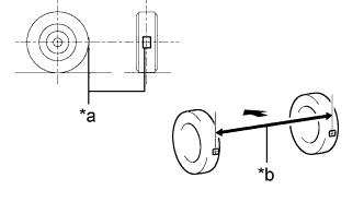 |
Put tread center marks on the rearmost points of the rear wheels and measure the distance between the marks (dimension B).
| *a | Tread Center Mark |
| *b | Dimension B |
| Front of the Vehicle |
Slowly push the vehicle straight ahead to cause the rear wheels to rotate 180° using the rear tire valve as a reference point.
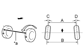 |
Measure the distance between the tread center marks on the front side of the rear wheels (dimension A).
| *a | Dimension A |
| Front of the Vehicle |
| Specified Condition |
| C + D: 0°13' +/- 0°10' (0.21° +/- 0.17°) |
| B - A: 2.5 +/- 2.0 mm (0.0984 +/- 0.0787in.) |