DTC P0101 Mass Air Flow Circuit Range / Performance Problem |
| DTC No. | DTC Detection Condition | Trouble Area |
| P0101 | All of the following conditions continue for more than 10 seconds (2 trip detection logic): (a) The engine is running. (b) The engine coolant temperature is 70°C (158°F) or higher. (c) The throttle position sensor voltage is 0.2 V or higher, and less than 2 V. (d) Average engine load value ratio is less than 0.85, or higher than 1.15 (varies with estimated engine load). Average engine load value ratio = Average engine load based on mass air flow meter sub-assembly output / Average engine load estimated from driving conditions (e) Average air fuel ratio is less than -20%, or higher than 20% |
|
| Related DTCs | P0101: Mass air flow meter rationality |
| Required Sensors/Components (Main) | Mass air flow meter sub-assembly |
| Required Sensors/Components (Related) | Crankshaft position sensor VVT sensor Engine coolant temperature sensor Throttle position sensor |
| Frequency of Operation | Continuous |
| Duration | 10 times |
| MIL Operation | 2 driving cycles |
| Sequence of Operation | None |
| Monitor runs whenever the following DTCs are not stored | None |
| All of the following conditions are met | - |
| Throttle position voltage | 0.2 V or higher, and less than 2 V |
| Time after engine start | 5 seconds or more |
| Battery voltage | 10.5 V or higher |
| Engine coolant temperature | 70°C (158°F) or higher |
| Estimated load | 30% or higher, and less than 70% |
| Mass air flow meter circuit fail (P0102, P0103) | Not detected |
| Intake air temperature sensor circuit fail (P0112, P0113) | Not detected |
| Engine coolant temperature sensor circuit fail (P0115, P0117, P0118) | Not detected |
| Crankshaft position sensor circuit fail (P0335) | Not detected |
| Throttle position sensor circuit fail (P0120, P0121, P0122, P0123, P0220, P0222, P0223, P2135) | Not detected |
| Canister pressure sensor circuit fail (P0452, P0453) | Not detected |
| Leak detection pump fail (P2401, P2402) | Not detected |
| Vent valve fail (P2419, P2420) | Not detected |
| Both of the following conditions are met | - |
| Average engine load value ratio | Less than 0.85, or higher than 1.15 (varies with estimated engine load) |
| Average air fuel ratio | Less than -20%, or higher than 20% |
| Techstream Display | Description |
| NORMAL |
|
| ABNORMAL |
|
| INCOMPLETE |
|
| N/A |
|
| 1.CHECK ANY OTHER DTCS OUTPUT (IN ADDITION TO DTC P0101) |
Connect the Techstream to the DLC3.
Turn the engine switch on (IG).
Turn the Techstream on.
Enter the following menus: Powertrain / Engine / Trouble Codes.
Read the DTCs.
| Result | Proceed to |
| DTC P0101 is output | A |
| DTC P0101 and other DTCs are output | B |
|
| ||||
| A | |
 |
| 2.CHECK INTAKE SYSTEM |
Check the intake system for vacuum leaks (Click here).
|
| ||||
| OK | |
|
| 3.CHECK PCV HOSE CONNECTIONS |
Check the PCV hose connections (Click here).
|
| ||||
| OK | |
|
| 4.REPLACE MASS AIR FLOW METER SUB-ASSEMBLY |
Replace the mass air flow meter sub-assembly (Click here).
| NEXT | |
|
| 5.CONFIRM WHETHER MALFUNCTION HAS BEEN SUCCESSFULLY REPAIRED |
Connect the Techstream to the DLC3.
Turn the engine switch on (IG).
Turn the Techstream on.
Clear the DTCs (Click here).
Turn the engine switch off and wait for at least 30 seconds.
Turn the engine switch on (IG).
Turn the Techstream on.
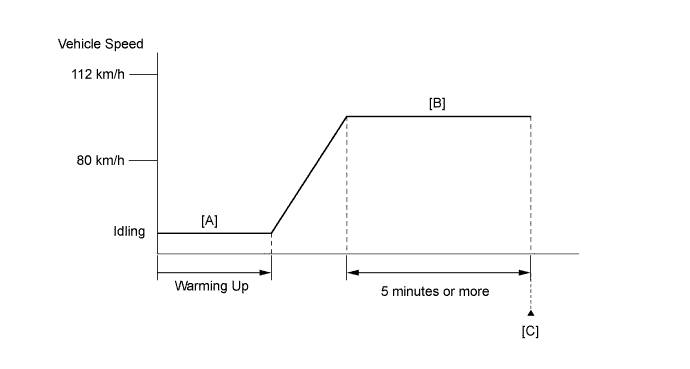
Start the engine and warm it up.
Drive the vehicle in accordance with the driving pattern described in Confirmation Driving Pattern.
Enter the following menus: Powertrain / Engine / Utility / All Readiness.
Input the DTC: P0101.
Check the DTC judgment result.
| Techstream Display | Description |
| NORMAL |
|
| ABNORMAL |
|
| INCOMPLETE |
|
| N/A |
|
| NEXT | ||
 | ||
| ||
