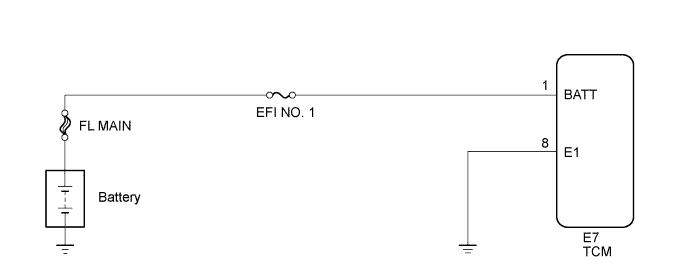
DTC P0560 System Voltage |
| DTC No. | DTC Detection Condition | Trouble Area |
| P0560 | Open in TCM back-up power source circuit. DTC is detected for 3 sec. or more (1 trip detection logic). |
|
| Related DTCs | P0560: TCM system voltage |
| Required Sensors/Components (Main) | TCM |
| Required Sensors/Components (Sub) | - |
| Frequency of Operation | Continuous |
| Duration | 3 seconds |
| MIL Operation | Immediate (MIL illuminated after next engine start) |
| Sequence of Operation | None |
| Monitor runs whenever following DTCs are not present: | None |
| Stand-by RAM | Initialized |
| TCM power source | Less than 3.5 V |
| 1.CHECK DTC OUTPUT |
Connect the Techstream to the DLC3.
Turn the engine switch on (IG).
Turn the Techstream on.
Enter the following menus: Powertrain / Engine / Trouble Codes.
Read the DTCs using the Techstream.
| Display (DTC Output) | Proceed to |
| No DTC | A |
| P0560 is output (engine control system) | B |
|
| ||||
| A | |
 |
| 2.INSPECT TCM (POWER SOURCE, GROUND) |
Disconnect the TCM connector.
Measure the voltage according to the value(s) in the table below.
| Tester Connection | Condition | Specified Condition |
| E7-1 (BATT) - E7-8 (E1) | Always | 11 to 14 V |
Measure the resistance according to the value(s) in the table below.
| Tester Connection | Condition | Specified Condition |
| E7-8 (E1) - Body ground | Always | Below 1 Ω |
|
| ||||
| OK | ||
 | ||
| ||
