 |
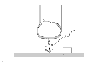
Using a dial indicator, check the runout of the tires.
- Maximum tire runout:
- 1.4 mm (0.0551 in.)
REAR WHEEL ALIGNMENT > ADJUSTMENT |
| 1. INSPECT TIRES |
Check the tires for wear and proper inflation pressure.
| Tire Size | Front kPa (kgf/cm2, psi) | Rear kPa (kgf/cm2, psi) |
| P205/65R16 94S | 240 (2.4, 35) | |
| P215/55R17 93V | 240 (2.4, 35)*1 210 (2.1, 30)*2 | |
| P225/45R18 91V | 230 (2.3, 33) | |
|
Using a dial indicator, check the runout of the tires.
| 2. MEASURE VEHICLE HEIGHT |
 |
Bounce the vehicle up and down at the corners to stabilize the suspension.
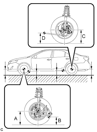
Measure the vehicle height.
| Engine | Tire Size | Front A - B | Rear C - D |
| 2AR-FE | 205/65R16 | 123 mm (4.84 in.) | 52 mm (2.05 in.) |
| 215/55R17 | 122 mm (4.80 in.)*1 114 mm (4.49 in.)*1, *4 | 51 mm (2.01 in.)*1 44 mm (1.73 in.)*1, *4 | |
| 125 mm (4.92 in.)*2 115 mm (4.53 in.)*2, *4 | 54 mm (2.13 in.)*2 46 mm (1.81 in.)*2, *4 | ||
| 124 mm (4.88 in.)*3 | 52 mm (2.05 in.)*3 | ||
| 225/45R18 | 123 mm (4.84 in.) | 51 mm (2.01 in.) | |
| 2GR-FE | 215/55R17 | 127 mm (5.00 in.) 117 mm (4.61 in.)*4 | 57 mm (2.24 in.) 48 mm (1.89 in.)*4 |
| 225/45R18 | 123 mm (4.84 in.) | 54 mm (2.13 in.) |
| 3. INSPECT CAMBER |
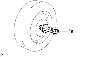 |
Install a camber-caster-kingpin gauge.
| *a | Camber-caster-kingpin Gauge |
Inspect the camber.
| Engine | Tire Size | Camber Inclination | Right-left Difference |
| 2AR-FE | 205/65R16 | -1°12' +/- 45' (-1.20° +/- 0.75°) | 45' (0.75°) or less |
| 215/55R17 | -1°11' +/- 45' (-1.18° +/- 0.75°)*1 -1°02' +/- 45' (-1.03° +/- 0.75°)*1, *4 | ||
| -1°14' +/- 45' (-1.23° +/- 0.75°)*2 -1°05' +/- 45' (-1.08° +/- 0.75°)*2, *4 | |||
| -1°12' +/- 45' (-1.20° +/- 0.75°)*3 | |||
| 225/45R18 | -1°12' +/- 45' (-1.20° +/- 0.75°) | ||
| 2GR-FE | 215/55R17 | -1°16' +/- 45' (-1.27° +/- 0.75°) -1°08' +/- 45' (-1.13° +/- 0.75°)*4 | |
| 225/45R18 | -1°14' +/- 45' (-1.23° +/- 0.75°) |
| 4. INSPECT TOE-IN |
Bounce the vehicle up and down at the corners to stabilize the suspension.
Release the parking brake and move the shift lever to N.
Push the vehicle straight ahead approximately 5 m (16.4 ft.). (Step A)
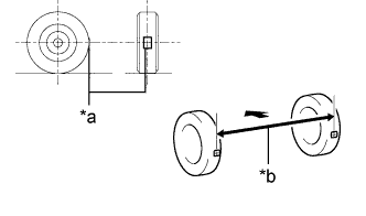 |
Put tread center marks on the rearmost points of the rear wheels and measure the distance between the marks (dimension B).
| *a | Tread Center Mark |
| *b | Dimension B |
 | Front of the Vehicle |
Slowly push the vehicle straight ahead to cause the rear wheels to rotate 180°. Use the rear tire valve as a reference point.
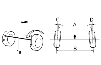 |
Measure the distance between the tread center marks on the front of the rear wheels (dimension A).
| *a | Dimension A |
| Front of the Vehicle |
| Specified Condition |
| C + D: 0°13' +/- 0°10' (0.21° +/- 0.17°) |
| B - A: 2.5 +/- 2.0 mm (0.0984 +/- 0.0787 in.) |
| 5. ADJUST TOE-IN |
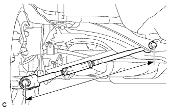 |
Measure the lengths of the right and left rear No. 2 suspension arms.
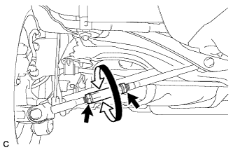 |
Loosen the 2 lock nuts.
If the length difference between the left and right rear No. 2 suspension arm assemblies is not within the specified range, adjust it by following the procedures below.
If the toe-in measurement is greater than the specified range (too much toe-out), extend the shorter rear No. 2 suspension arm by rotating the adjusting tube so that the length difference is within the specified range.
If the toe-in measurement is less than the specified range (too much toe-in), shorten the longer rear No. 2 suspension arm by rotating the adjusting tube so that the length difference is within the specified range.
Measure the toe-in.
Turn the right and left adjusting tubes by an equal amount to adjust toe-in.
Tighten the lock nuts while securing the adjusting tube in the order indicated below: