 |
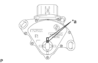
Align the protrusions of the park/neutral position switch.
| *a | Protrusion |
PARK / NEUTRAL POSITION SWITCH > INSTALLATION |
| 1. INSTALL PARK/NEUTRAL POSITION SWITCH ASSEMBLY |
Move the shift lever to N.
|
Align the protrusions of the park/neutral position switch.
| *a | Protrusion |
Install the park/neutral position switch to the control shaft with the 2 bolts.
Install the control shaft lever to the control shaft with the nut and washer.
Connect the connector to the park/neutral position switch.
| 2. CONNECT TRANSMISSION CONTROL CABLE ASSEMBLY |
Connect the transmission control cable assembly to the transmission control cable bracket with a new clip.
Connect the transmission control cable assembly to the control shaft lever with the nut.
| 3. INSTALL AIR CLEANER CASE SUB-ASSEMBLY |
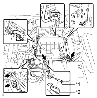 |
Install the air cleaner case sub-assembly to the inlet No. 1 air cleaner.
Insert the projection of the air cleaner case sub-assembly to the hole of the No. 2 air cleaner bracket as shown in the illustration.
| *1 | Air Cleaner Case Sub-assembly |
| *2 | Inlet No. 1 Air Cleaner |
| *a | Projection |
| *b | Hole |
Tighten the 2 bolts.
Connect the wire harness clamp, connector, vacuum hose and No. 1 fuel vapor feed hose.
| 4. INSTALL AIR CLEANER FILTER ELEMENT SUB-ASSEMBLY |
| 5. INSTALL AIR CLEANER CAP SUB-ASSEMBLY |
Connect the air cleaner cap sub-assembly to the throttle with motor body assembly with the hose clamp.
Install the air cleaner cap with hose to the air cleaner case with the 2 clamps.
Connect the wire harness clamp and mass air flow meter connector.
Connect the 3 hoses.
Connect the ventilation hose.
Connect the mass air flow meter connector and wire harness clamp.
| 6. INSTALL INLET NO. 2 AIR CLEANER |
Install the inlet No. 2 air cleaner to the air cleaner case sub-assembly with the 2 bolts.
Connect the 2 wire harness clamps and vacuum hose clamp.
| 7. INSTALL COOL AIR INTAKE DUCT SEAL |
Install the cool air intake duct seal with the 7 clips.
| 8. INSPECT PARK/NEUTRAL POSITION SWITCH ASSEMBLY OPERATION |
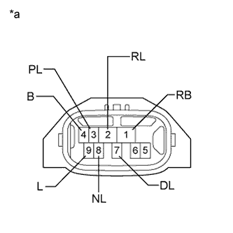 |
Measure the resistance according to the value(s) in the table below when the shift lever is moved to each position.
| Tester Connection | Shift Lever Position | Specified Condition |
| 1 (RB) - 3 (PL) 4 (B) - 9 (L) | P | Below 1 Ω |
| Except P | 10 kΩ or higher | |
| 1 (RB) - 2 (RL) | R | Below 1 Ω |
| Except R | 10 kΩ or higher | |
| 1 (RB) - 8 (NL) 4 (B) - 9 (L) | N | Below 1 Ω |
| Except N | 10 kΩ or higher | |
| 1 (RB) - 7 (DL) | D, S, "+" or "-" | Below 1 Ω |
| Except D, S, "+" and "-" | 10 kΩ or higher |
| *a | Component without harness connected (Park/Neutral Position Switch) |
| 9. INSPECT SHIFT LEVER POSITION |
When the shift lever is moved from P to R with the engine switch on (IG) and brake pedal depressed, make sure that the shift lever moves smoothly and correctly into position.
Start the engine and make sure that the vehicle moves forward when the shift lever is moved from N to D and moves rearward when the shift lever is moved to R.
| 10. ADJUST SHIFT LEVER POSITION |
Move the shift lever to N.
Remove the console box (Click here).
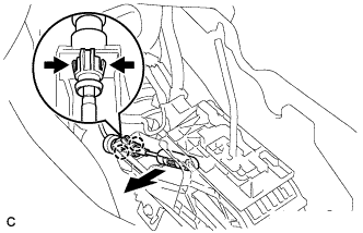 |
Disconnect the end of the transmission control cable assembly from the lower shift lever assembly
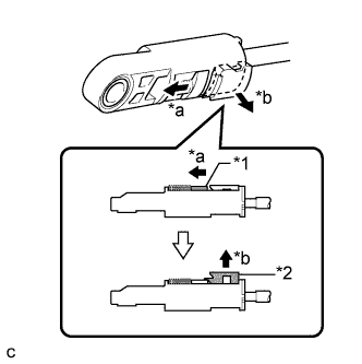 |
Slide the slider of the transmission control cable in the direction indicated by the arrow and pull the lock piece outward.
| *1 | Slider |
| *2 | Lock Piece |
| *a | Slide |
| *b | Pull |
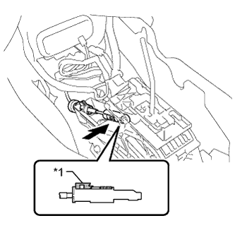 |
Install the end of the transmission control cable to the shift lever assembly.
| *1 | Lock Piece |
Push the lock piece into the adjuster case.
After adjusting the shift lever position, check the operation and function of the shift lever. If there is a problem, adjust the position again.
Install the console box (Click here).