 |
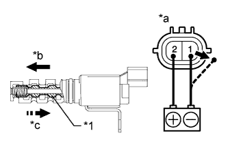
Connect a positive (+) lead from the battery to terminal 1 and a negative (-) lead to terminal 2, and check the movement of the valve.
| *1 | Valve |
| *a | Component without harness connected (Camshaft Timing Oil Control Valve) |
| *b | When applied |
| *c | When cut off |
- OK:
Condition Specified Condition Battery positive (+) voltage is applied Valve moves in left arrow direction shown in illustration Battery positive (+) voltage is cut off Valve moves in right arrow direction shown in illustration
- NOTICE:
- Confirm that the valve moves freely and does not stick in any position.
- HINT:
- Accumulation of foreign matter can cause minor pressure leaks. Minor pressure leaks will cause the camshaft to advance or retard, and this will cause a DTC to be set.