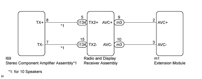
NAVIGATION SYSTEM (for Radio and Display Type) > AVC-LAN Circuit |
| 1.INSPECT RADIO AND DISPLAY RECEIVER ASSEMBLY |
Disconnect the radio and display receiver assembly connectors.
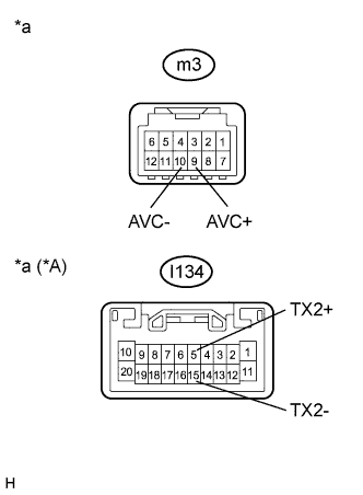 |
Measure the resistance according to the value(s) in the table below.
| Tester Connection | Condition | Specified Condition |
| m3-9 (AVC+) - m3-10 (AVC-) | Always | 60 to 80 Ω |
| I134-5 (TX2+) - I134-15 (TX2-)*1 | Always | 60 to 80 Ω |
| *A | for 10 Speakers |
| *a | Component without harness connected (Radio and Display Receiver Assembly) |
|
| ||||
| OK | |
 |
| 2.CHECK HARNESS AND CONNECTOR (AVC-LAN CIRCUIT) |
Disconnect the radio and display receiver assembly connector.
Disconnect the extension module connector.
Disconnect the stereo component amplifier assembly connector (for 10 Speakers).
Measure the resistance according to the value(s) in the table below.
| Tester Connection | Condition | Specified Condition |
| m3-9 (AVC+) - m1-2 (AVC+) | Always | Below 1 Ω |
| m3-10 (AVC-) - m1-3 (AVC-) | Always | Below 1 Ω |
| I134-5 (TX2+) - I69-8 (TX+)*1 | Always | Below 1 Ω |
| I134-15 (TX2-) - I69-7 (TX-)*1 | Always | Below 1 Ω |
| m3-9 (AVC+) - Body ground | Always | 10 kΩ or higher |
| m3-10 (AVC-) - Body ground | Always | 10 kΩ or higher |
| I134-5 (TX2+) - Body ground*1 | Always | 10 kΩ or higher |
| I134-15 (TX2-) - Body ground*1 | Always | 10 kΩ or higher |
|
| ||||
| OK | |
|
| 3.INSPECT MALFUNCTIONING PARTS |
Disconnect and reconnect each slave unit one by one until the master unit returns to normal operation.
|
| ||||
| OK | ||
 | ||
| ||
