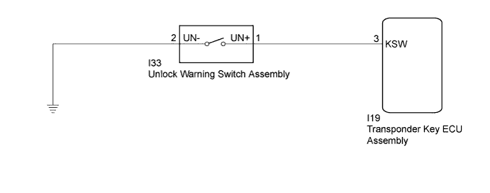
DTC B2780 Push Switch / Key Unlock Warning Switch Malfunction |
| DTC No. | DTC Detection Condition | Trouble Area |
| B2780 | "Unlock warning switch ON" is not detected when the key is in the ignition key cylinder. |
|
| 1.READ VALUE USING TECHSTREAM |
Connect the Techstream to the DLC3.
Turn the ignition switch to ON.
Turn the Techstream on.
Enter the following menus: Body Electrical / Immobiliser / Data List.
Read the Data List according to the display on the Techstream.
| Tester Display | Measurement Item/Range | Normal Condition | Diagnostic Note |
| Key SW | Unlock warning switch signal/ON or OFF | ON: Key in ignition key cylinder OFF: No key in ignition key cylinder | - |
|
| ||||
| OK | ||
 | ||
| ||
| 2.INSPECT UNLOCK WARNING SWITCH ASSEMBLY |
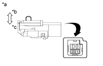 |
Remove the unlock warning switch assembly (Click here).
Measure the resistance according to the value(s) in the table below.
| Tester Connection | Switch Condition | Specified Condition |
| 1 - 2 | Pushed (Key set) | Below 1 Ω |
| 1 - 2 | Free (Key removed) | 10 kΩ or higher |
| *a | Component without harness connected (Unlock Warning Switch Assembly) |
| *b | Free |
| *c | Pushed |
|
| ||||
| OK | |
 |
| 3.CHECK HARNESS AND CONNECTOR (UNLOCK WARNING SWITCH - TRANSPONDER KEY ECU AND BODY GROUND) |
Disconnect the transponder key ECU assembly connector.
Measure the resistance according to the value(s) in the table below.
| Tester Connection | Condition | Specified Condition |
| I19-3 (KSW) - I33-1 (UN+) | Always | Below 1 Ω |
| I19-3 (KSW) - Body ground | Always | 10 kΩ or higher |
| I33-2 (UN-) - Body ground | Always | Below 1 Ω |
|
| ||||
| OK | ||
| ||
| ||

