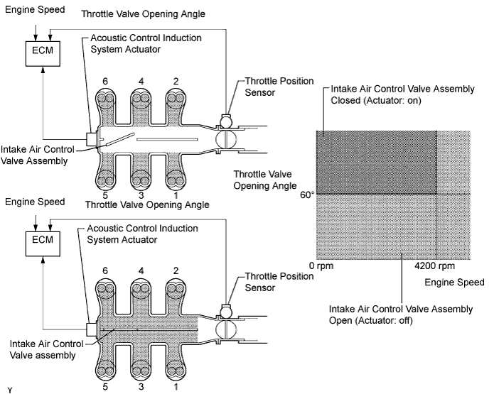
SFI SYSTEM > ACIS Control Circuit |
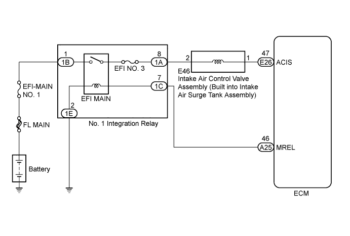
| 1.PERFORM ACTIVE TEST USING TECHSTREAM (ACTIVATE THE VSV FOR INTAKE CONTROL) |
Connect the Techstream to the DLC3.
Turn the engine switch on (IG).
Turn the Techstream on.
Enter the following menus: Powertrain / Engine / Active Test / Activate the VSV for Intake Control.
Check if operating noise can be heard when operating the intake air control valve assembly using the Techstream.
|
| ||||
| OK | ||
 | ||
| ||
| 2.INSPECT INTAKE AIR SURGE TANK ASSEMBLY (INTAKE AIR CONTROL VALVE ASSEMBLY OPERATION) |
Inspect the intake air surge tank assembly (intake air control valve assembly) (Click here).
|
| ||||
| OK | |
 |
| 3.CHECK TERMINAL VOLTAGE (POWER SOURCE OF INTAKE AIR CONTROL VALVE ASSEMBLY) |
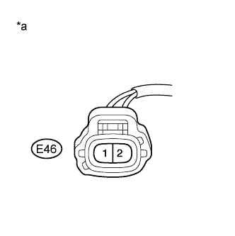 |
Disconnect the intake air control valve assembly connector.
Turn the engine switch on (IG).
Measure the voltage according to the value(s) in the table below.
| Tester Connection | Switch Condition | Specified Condition |
| E46-2 - Body ground | Engine switch on (IG) | 11 to 14 V |
| *a | Front view of wire harness connector (to Intake Air Control Valve Assembly) |
|
| ||||
| OK | |
|
| 4.CHECK HARNESS AND CONNECTOR (INTAKE AIR CONTROL VALVE ASSEMBLY - ECM) |
Disconnect the intake air control valve assembly connector.
Disconnect the ECM connector.
Measure the resistance according to the value(s) in the table below.
| Tester Connection | Condition | Specified Condition |
| E46-1 - E26-47 (ACIS) | Always | Below 1 Ω |
| E46-1 or E26-47 (ACIS) - Body ground | Always | 10 kΩ or higher |
|
| ||||
| OK | ||
| ||
| ||
| 5.CHECK HARNESS AND CONNECTOR (NO. 1 INTEGRATION RELAY - INTAKE AIR CONTROL VALVE ASSEMBLY) |
Remove the No. 1 integration relay from the engine room relay block and junction block assembly.
Disconnect the intake air control valve assembly connector.
Measure the resistance according to the value(s) in the table below.
| Tester Connection | Condition | Specified Condition |
| 1A-8 - E46-2 | Always | Below 1 Ω |
| 1A-8 or E46-2 - Body ground | Always | 10 kΩ or higher |
|
| ||||
| OK | ||
| ||
| ||

