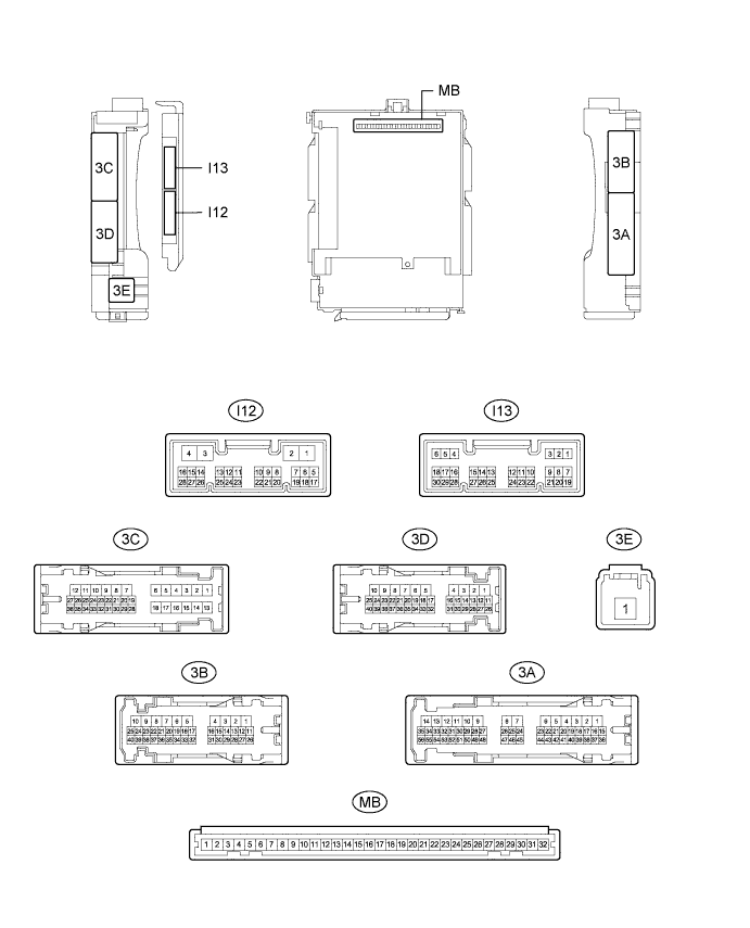
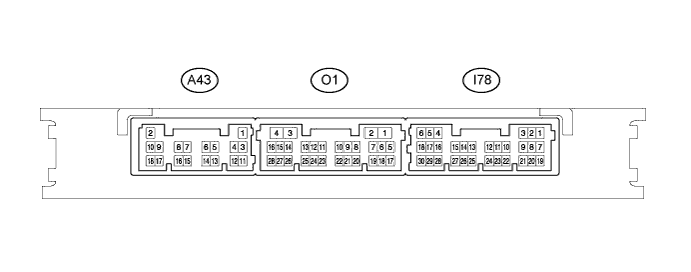
Terminal No. (Symbol)
| Wiring Color
| Terminal Description
| Condition
| Specified Condition
|
3A-23 - Body ground
| L - Body ground
| Light cut relay drive output
| Light cut relay off
| 11 to 14 V
|
Light cut relay on
| Below 1 V
|
3B-34 - Body ground*1
| V - Body ground
| Ignition key cylinder light drive output
| Ignition switch off, ignition key cylinder light off (when operated by illuminated entry system)
| 11 to 14 V
|
Ignition switch off, ignition key cylinder light on (when operated by illuminated entry system)
| Below 1 V
|
3B-35 - Body ground
| LG - Body ground
| Interior lights drive output
| Ignition switch off, interior lights off (when operated by illuminated entry system)
| 11 to 14 V
|
Ignition switch off, interior lights on (when operated by illuminated entry system)
| Below 1 V
|
3B-13 - Body ground
| LG - Body ground
| Front door courtesy light LH drive output
| Ignition switch off, front door courtesy light LH off
| 11 to 14 V
|
Ignition switch off, front door courtesy light LH on
| Below 1 V
|
3C-8 - Body ground
| B - Body ground
| Luggage compartment room light drive output
| Ignition switch off, luggage compartment room light off
| 11 to 14 V
|
Ignition switch off, luggage compartment room light on
| Below 1 V
|
3C-15 - Body ground
| L - Body ground
| Front door courtesy light switch LH input
| Front door LH open
| Below 1 V
|
Front door LH closed
| 11 to 14 V
|
I13-19 (FRCY) - Body ground
| Y - Body ground
| Front door courtesy light switch RH input
| Front door RH open
| Below 1 V
|
Front door RH closed
| 11 to 14 V
|
I13-1 (LCTY) - Body ground
| P - Body ground
| Rear door courtesy light switch LH input
| Rear door LH open
| Below 1 V
|
Rear door LH closed
| Pulse generation
|
I13-6 (RCTY) - Body ground
| B - Body ground
| Rear door courtesy light switch RH input
| Rear door RH open
| Below 1 V
|
Rear door RH closed
| Pulse generation
|
3C-9 - Body ground
| W - Body ground
| Luggage compartment door courtesy light switch input
| Luggage compartment door open
| Below 1 V
|
Luggage compartment door closed
| 11 to 14 V
|
I13-7 (LSFL) - Body ground
| V - Body ground
| Front door unlock detection switch LH input
| Front door LH locked
| Pulse generation
|
Front door LH unlocked
| Below 1 V
|
I13-18 (LSFR) - Body ground
| W - Body ground
| Front door unlock detection switch RH input
| Front door RH locked
| Pulse generation
|
Front door RH unlocked
| Below 1 V
|
3C-17 - Body ground
| LG - Body ground
| Rear door unlock detection switch LH input
| Rear door LH and rear door RH locked
| Pulse generation
|
Rear door LH or rear door RH unlocked
| Below 1 V
|
3A-53 - Body ground
| Y - Body ground
| Rear door unlock detection switch RH input
| Rear door LH and rear door RH locked
| Pulse generation
|
Rear door LH or rear door RH unlocked
| Below 1 V
|