AUTOMATIC TRANSAXLE UNIT > INSPECTION |
| 1. INSPECT TRANSMISSION OIL CLEANER MAGNET |
![]() |
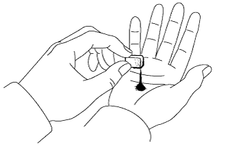
Use the removed magnets to collect any steel chips. Examine the chips and particles in the pan and on the magnets to determine what type of wear has occurred in the transaxle:
| 2. INSPECT INPUT SHAFT SUB-ASSEMBLY |
![]() |
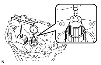
Using a dial indicator, measure the input shaft end play.
| 3. INSPECT NO. 2 CLUTCH DISC |
![]() |
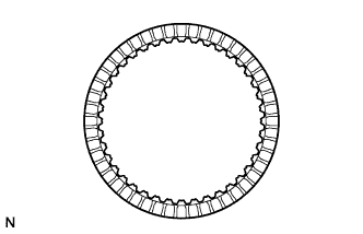
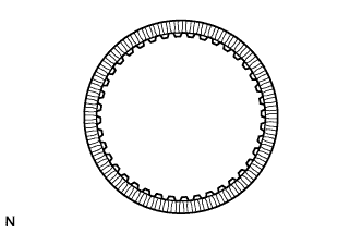
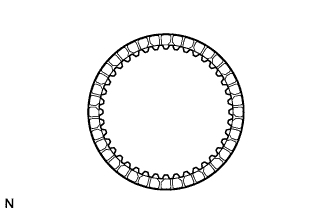
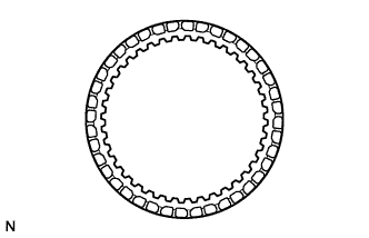
Check if the contact surfaces of the discs, plates and flange are worn or burnt.
| 4. INSPECT PLANETARY SUN GEAR SUB-ASSEMBLY |
![]() |
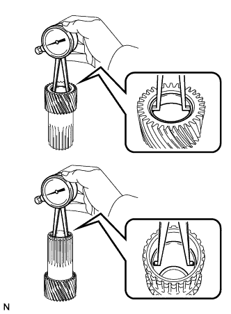
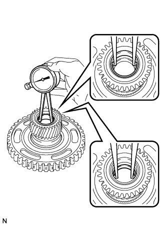
Using a dial indicator, measure the inside diameter of the bushings of the planetary sun gear.
| 5. INSPECT NO. 1 CLUTCH DISC |
![]() |
Check if the contact surfaces of the discs, plates and flange are worn or burnt.
| 6. INSPECT NO. 3 BRAKE DISC |
![]() |
Check if the contact surfaces of the discs, plates and flanges are worn or burnt.
| 7. INSPECT UNDERDRIVE PLANETARY GEAR ASSEMBLY |
![]() |
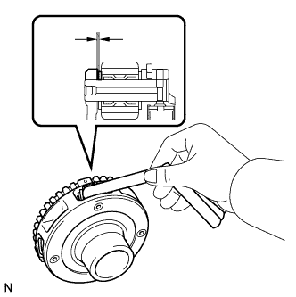
Using a feeler gauge, measure the clearance between the underdrive planetary gear and the pinion gear at 4 points.
| 8. INSPECT REAR PLANETARY SUN GEAR ASSEMBLY |
![]() |
Using a dial indicator, measure the inside diameter of the bushing of the rear planetary sun gear sub-assembly.
| 9. INSPECT NO. 1 BRAKE DISC |
![]() |
Check if the contact surfaces of the discs, plates and flange are worn or burnt.
| 10. INSPECT 2ND BRAKE PISTON RETURN SPRING SUB-ASSEMBLY |
![]() |
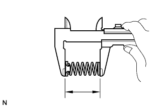
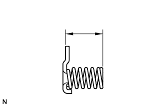
Using a vernier caliper, measure the free length of the 3 2nd brake piston return springs including the spring seats.
| 11. INSPECT ONE-WAY CLUTCH ASSEMBLY |
![]() |
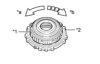
Temporarily install the one-way clutch assembly to the planetary ring gear.
| *1 | Planetary Ring Gear |
| *2 | One-way Clutch Assembly |
| *a | Free |
| *b | Lock |
Make sure that the one-way clutch assembly turns freely counterclockwise and locks when turned clockwise.
If the one-way clutch assembly does not operate normally, replace it.
| 12. INSPECT PLANETARY GEAR ASSEMBLY |
![]() |
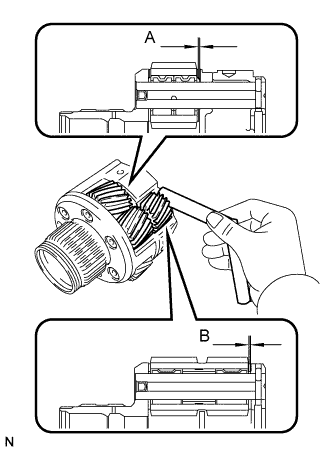
Using a feeler gauge, measure the clearance between the planetary gear case and each pinion gear at points A and B.
| 13. INSPECT NO. 2 BRAKE DISC |
![]() |
Check if the contact surfaces of the discs, plates and flange are worn or burnt.
| 14. INSPECT 1ST AND REVERSE BRAKE RETURN SPRING SUB-ASSEMBLY |
![]() |
Using a vernier caliper, measure the free length of the 1st and reverse brake return spring together with the spring seat.
| 15. INSPECT CLEARANCE OF NO. 2 BRAKE |
![]() |
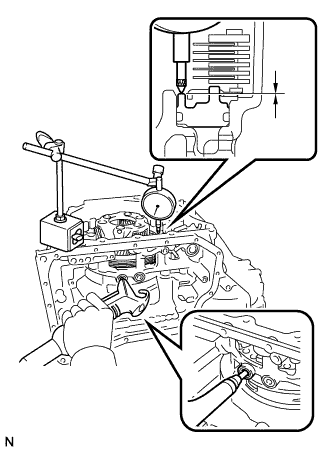
Using a dial indicator, measure the clearance of the No. 2 brake while applying compressed air (200 kPa, 2.0 kgf/cm2, 29 psi).
| Mark | Thickness |
| 40 | 4.0 (0.157) |
| 41 | 4.1 (0.161) |
| 42 | 4.2 (0.165) |
| 43 | 4.3 (0.169) |
| 44 | 4.4 (0.173) |
| 16. INSPECT CLEARANCE OF NO. 1 BRAKE |
![]() |
Using a dial indicator, measure the clearance of the No. 1 brake while applying compressed air (200 kPa, 2.0 kgf/cm2, 29 psi).
| Mark | Thickness |
| 30 | 3.0 (0.118) |
| 31 | 3.1 (0.122) |
| 32 | 3.2 (0.126) |
| 33 | 3.3 (0.130) |
| 34 | 3.4 (0.134) |
| 35 | 3.5 (0.138) |
| 17. INSPECT CLEARANCE OF NO. 3 BRAKE |
![]() |
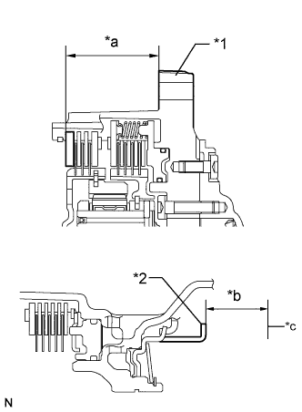
Using a vernier caliper and a straightedge, measure the distance shown in the illustration (Dimension A) while a load of 500 N (51 kgf, 112.4 lbf) is being applied to the flange.
| *1 | Front Oil Pump Assembly |
| *2 | No. 3 Brake Piston |
| *a | Dimension A |
| *b | Dimension B |
| *c | Contact surface of front oil pump assembly |
Using a vernier caliper and a straightedge, measure the distance shown in the illustration (Dimension B).
Calculate the clearance value using the following formula:
Clearance = Dimension B - Dimension A
| Mark | Thickness |
| 38 | 3.80 (0.150) |
| 39 | 3.90 (0.154) |
| 40 | 4.00 (0.157) |
| 41 | 4.10 (0.161) |
| 42 | 4.20 (0.165) |
| 43 | 4.30 (0.169) |
| 18. INSPECT CLEARANCE OF NO. 1 CLUTCH DISC |
![]() |
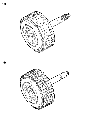
| *a | Transaxle serial number 2########## |
| *b | Transaxle serial number 3########## |
![]() |
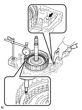
Install the direct multiple disc clutch assembly onto the rear transaxle cover sub-assembly.
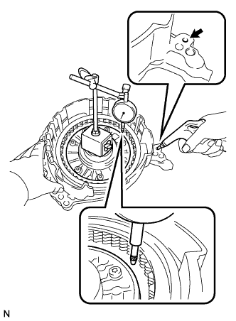
Using a dial indicator, measure the No. 1 clutch pack clearance while applying and releasing compressed air (200 kPa, 2.0 kgf/cm2, 29 psi).
| Mark | Thickness |
| 30 | 3.0 (0.118) |
| 31 | 3.1 (0.122) |
| 32 | 3.2 (0.126) |
| 33 | 3.3 (0.130) |
| 34 | 3.4 (0.134) |
| 35 | 3.5 (0.138) |
| 36* | 3.6 (0.142)* |
| 19. INSPECT CLEARANCE OF NO. 2 CLUTCH DISC |
![]() |
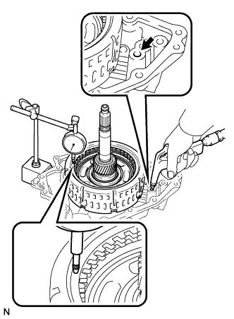
Install the direct multiple disc clutch assembly onto the rear transaxle cover sub-assembly.
Using a dial indicator, measure the No. 2 clutch pack clearance while applying and releasing compressed air (200 kPa, 2.0 kgf/cm2, 29 psi).
| Mark | Thickness |
| 30 | 3.0 (0.118) |
| 31 | 3.1 (0.122) |
| 32 | 3.2 (0.126) |
| 33 | 3.3 (0.130) |
| 34 | 3.4 (0.134) |
| 35 | 3.5 (0.138) |
| 36* | 3.6 (0.142)* |