 |
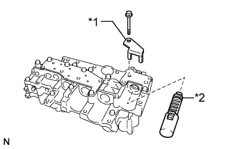
Coat the shift solenoid valve SL4 and bolt with ATF.
| *1 | Lock Plate |
| *2 | Solenoid Valve SL4 |
VALVE BODY ASSEMBLY > REASSEMBLY |
| 1. INSTALL SHIFT SOLENOID VALVE SL4 |
|
Coat the shift solenoid valve SL4 and bolt with ATF.
| *1 | Lock Plate |
| *2 | Solenoid Valve SL4 |
Install the shift solenoid valve SL4 and lock plate to the valve body assembly with the bolt.
| 2. INSTALL SHIFT SOLENOID VALVE SL3 |
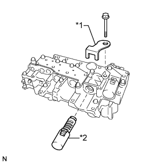 |
Coat the shift solenoid valve SL3 and bolt with ATF.
| *1 | Lock Plate |
| *2 | Solenoid Valve SL3 |
Install the shift solenoid valve SL3 and lock plate to the valve body assembly with the bolt.
| 3. INSTALL SHIFT SOLENOID VALVE SL1 |
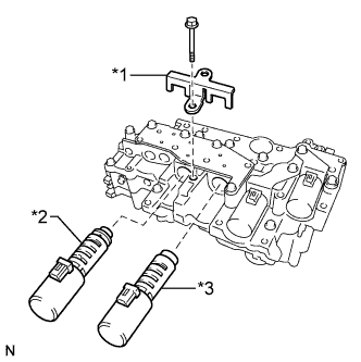 |
Coat the shift solenoid valve SL1 with ATF.
| *1 | Lock Plate |
| *2 | Solenoid Valve SL2 |
| *3 | Solenoid Valve SL1 |
Install the shift solenoid valve SL1 to the valve body assembly.
| 4. INSTALL SHIFT SOLENOID VALVE SL2 |
Coat the shift solenoid valve SL2 and bolt with ATF.
Install the shift solenoid valve SL2 and lock plate to the valve body assembly with the bolt.
| 5. INSTALL SHIFT SOLENOID VALVE SLU |
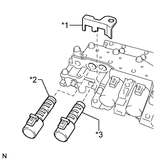 |
Coat the shift solenoid valve SLU with ATF.
| *1 | Lock Plate |
| *2 | Solenoid Valve SLT |
| *3 | Solenoid Valve SLU |
Install the shift solenoid valve SLU to the valve body assembly.
| 6. INSTALL SHIFT SOLENOID VALVE SLT |
Coat the shift solenoid valve SLT with ATF.
Install the shift solenoid valve SLT and lock plate to the valve body assembly.
| 7. INSTALL SHIFT SOLENOID VALVE SL |
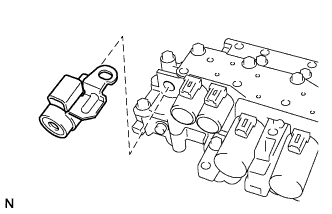 |
Coat the shift solenoid valve SL with ATF.
Install the shift solenoid valve SL to the valve body assembly.
| 8. INSTALL ATF TEMPERATURE SENSOR ASSEMBLY |
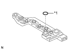 |
Coat a new O-ring with ATF and install it to the ATF temperature sensor assembly.
| *1 | O-ring |
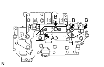 |
Coat the 4 bolts with ATF.
| *1 | Clamp |
Install the ATF temperature sensor assembly and clamp to the valve body assembly with the 4 bolts.
| 9. INSTALL TRANSMISSION WIRE |
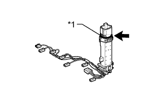 |
Coat the O-ring with ATF.
| *1 | O-ring |
Coat the bolt with ATF.
Install the transmission wire and lock plate to the valve body with the bolt.
Install the transmission wire to the clamp.
Connect the 9 connectors.