CYLINDER HEAD GASKET > REMOVAL |
| 1. REMOVE CAMSHAFT |
| 2. REMOVE NO. 2 CAMSHAFT |
Remove the No. 2 camshaft.
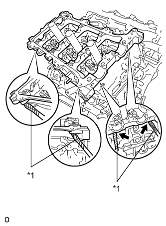
| 3. REMOVE CAMSHAFT HOUSING SUB-ASSEMBLY RH |
![]() |
Remove the camshaft housing sub-assembly RH by prying between the cylinder head and camshaft housing sub-assembly RH with a screwdriver.
| *1 | Protective Tape |
| 4. REMOVE CAMSHAFT TIMING GEARS AND NO. 2 CHAIN (for Bank 2) |
![]() |
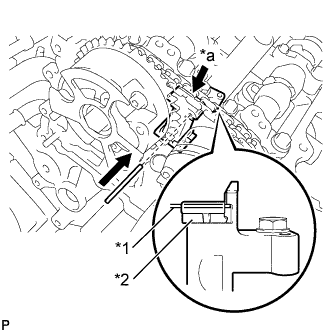
While pushing down the No. 3 chain tensioner assembly, insert a pin of 1.0 mm (0.0394 in.) diameter into the hole to hold the No. 3 chain tensioner assembly.
| *1 | Pin |
| *2 | Plunger |
| *a | Push |
![]() |
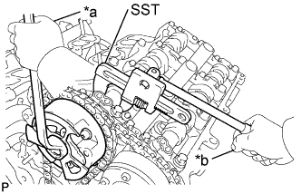
Using SST to hold the hexagonal portion of each camshaft, loosen the flange bolts of the camshaft timing gear assembly and the camshaft timing exhaust gear assembly.
| *a | Turn |
| *b | Hold |
Remove the 2 bolts and the camshaft timing gear together with the No. 2 chain.
| 5. REMOVE NO. 3 CHAIN TENSIONER ASSEMBLY |
![]() |
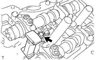
Remove the bolt and No. 3 chain tensioner assembly.
| 6. REMOVE CAMSHAFT BEARING CAP (for Bank 2) |
![]() |
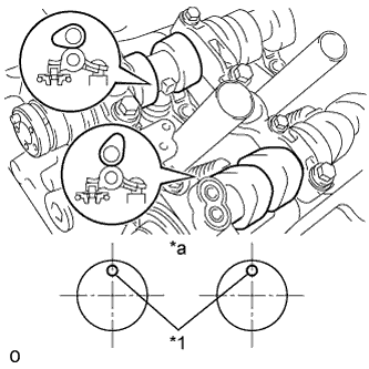
Check that the camshafts are positioned as shown in the illustration.
| *1 | Knock Pin |
| *a | Front View |
![]() |
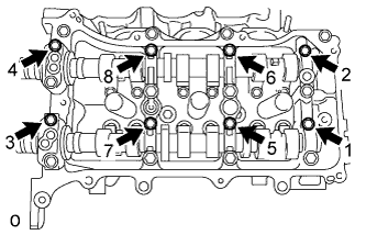
Uniformly loosen and remove the 8 bearing cap bolts in several steps and in the sequence shown in the illustration.
![]() |
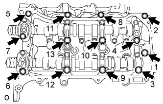
Uniformly loosen and remove the 13 bearing cap bolts in several steps and in the sequence shown in the illustration.
Remove the 5 camshaft bearing caps.
| 7. REMOVE NO. 3 CAMSHAFT |
Remove the No. 3 camshaft.
| 8. REMOVE NO. 4 CAMSHAFT |
Remove the No. 4 camshaft.
| 9. REMOVE CAMSHAFT HOUSING SUB-ASSEMBLY LH |
![]() |
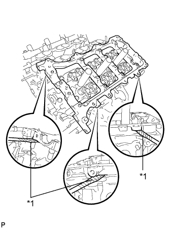
Remove the camshaft housing sub-assembly LH by prying between the cylinder head and camshaft housing sub-assembly LH with a screwdriver.
| *1 | Protective Tape |
| 10. REMOVE NO. 1 VALVE ROCKER ARM SUB-ASSEMBLY |
Remove the 24 valve rocker arms.
| 11. REMOVE VALVE LASH ADJUSTER ASSEMBLY |
Remove the 24 valve lash adjuster assemblies from the cylinder head.
| 12. REMOVE VALVE STEM CAP |
Remove the 24 valve stem caps.
| 13. REMOVE WATER OUTLET |
![]() |
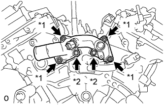
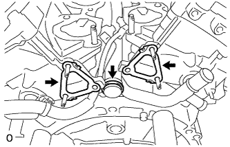
Remove the 2 bolts, 4 nuts and water outlet.
| *1 | Nut |
| *2 | Bolt |
![]() |
Remove the 2 gaskets and O-ring.
| 14. REMOVE CYLINDER HEAD SUB-ASSEMBLY RH |
![]() |
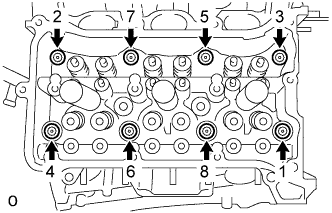
Using a 10 mm bi-hexagon wrench, uniformly loosen the 8 cylinder head bolts in the sequence shown in the illustration. Remove the 8 cylinder head bolts and plate washers.
Remove the cylinder head sub-assembly RH.
| 15. REMOVE CYLINDER HEAD GASKET RH |
Remove the cylinder head gasket RH.
| 16. REMOVE CYLINDER HEAD SUB-ASSEMBLY LH |
![]() |
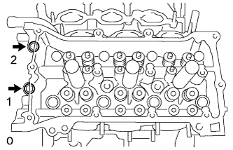
Uniformly loosen and remove the 2 cylinder head set bolts in several steps and in the sequence shown in the illustration.
![]() |
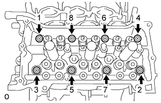
Using a 10 mm bi-hexagon wrench, uniformly loosen the 8 bolts in the sequence shown in the illustration. Remove the 8 cylinder head bolts and plate washers.
Remove the cylinder head sub-assembly LH.
| 17. REMOVE CYLINDER HEAD GASKET LH |
Remove the cylinder head gasket LH.