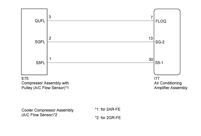
DTC B1479/79 Flow Sensor Circuit |
| DTC No. | DTC Detection Condition | Trouble Area |
| B1479/79 | Open or short in A/C flow sensor circuit |
|
| 1.CONFIRM MODEL |
| Result | Proceed to |
| for 2AR-FE | A |
| for 2GR-FE | B |
|
| ||||
| A | |
 |
| 2.READ VALUE USING TECHSTREAM |
Connect the Techstream to the DLC3.
Turn the ignition switch to ON.
Turn the Techstream on.
Enter the following menus: Body Electrical / Air Conditioner / Data List.
Check the value(s) by referring to the table below.
| Tester Display | Measurement Item/Range | Normal Condition | Diagnostic Note |
| Flow Sensor | A/C flow sensor / Min.: 0.0 V Max.: 5.0 V | A/C on, Blower switch HI: 0.7 to 3.8 V A/C off, Blower switch off: 3.8 to 4.2 V | A/C flow sensor is malfunctioning when a constant value between 0.7 and 4.2 V is displayed continuously for more than 4 seconds. |
| Result | Proceed to |
| OK (When troubleshooting according to Problem Symptoms Table) | A |
| OK (When troubleshooting according to the DTC) | B |
| NG (When a constant value between 0.7 and 4.2 V is displayed continuously for more than 4 seconds) | C |
|
| ||||
|
| ||||
| A | |
|
| 3.READ VALUE USING TECHSTREAM |
Connect the Techstream to the DLC3.
Turn the ignition switch to ON.
Turn the Techstream on.
Enter the following menus: Body Electrical / Air Conditioner / Data List.
Check the value(s) by referring to the table below.
| Tester Display | Measurement Item/Range | Normal Condition | Diagnostic Note |
| A/C Cutoff Signal | A/C control cutoff signal / OFF or ON | A/C switch on: OFF A/C switch off: ON | - |
| Result | Proceed to |
| Value in Data List indicates OFF | A |
| Value in Data List indicates ON | B |
|
| ||||
| A | |
|
| 4.REPLACE COMPRESSOR ASSEMBLY WITH PULLEY (A/C FLOW SENSOR) |
Replace the compressor assembly with pulley (A/C flow sensor) (Click here).
Check for the DTC.
| Result | Proceed to |
| DTC B1479/79 is not output | A |
| DTC B1479/79 is output | B |
|
| ||||
| A | ||
 | ||
| ||
| 5.CHECK HARNESS AND CONNECTOR (COMPRESSOR ASSEMBLY WITH PULLEY (A/C FLOW SENSOR) - AIR CONDITIONING AMPLIFIER ASSEMBLY) |
Disconnect the I77 air conditioning amplifier assembly connector.
Disconnect the E75 compressor assembly with pulley (A/C flow sensor) connector.
Measure the resistance according to the value(s) in the table below.
| Tester Connection | Condition | Specified Condition |
| I77-7 (FLOQ) - E75-3 (QUFL) | Always | Below 1 Ω |
| I77-13 (SG-2) - E75-2 (SGFL) | Always | Below 1 Ω |
| I77-30 (S5-1) - E75-1 (S5FL) | Always | Below 1 Ω |
| I77-7 (FLOQ) - Body ground | Always | 10 kΩ or higher |
| I77-13 (SG-2) - Body ground | Always | 10 kΩ or higher |
| I77-30 (S5-1) - Body ground | Always | 10 kΩ or higher |
|
| ||||
| OK | ||
| ||
| ||
| 6.READ VALUE USING TECHSTREAM |
Connect the Techstream to the DLC3.
Turn the ignition switch to ON.
Turn the Techstream on.
Enter the following menus: Body Electrical / Air Conditioner / Data List.
Check the value(s) by referring to the table below.
| Tester Display | Measurement Item/Range | Normal Condition | Diagnostic Note |
| Flow Sensor | A/C flow sensor / Min.: 0.0 V Max.: 5.0 V | A/C on, Blower switch HI: 0.7 to 3.8 V A/C off, Blower switch off: 3.8 to 4.2 V | A/C flow sensor is malfunctioning when a constant value between 0.7 and 4.2 V is displayed continuously for more than 4 seconds. |
| Result | Proceed to |
| OK (When troubleshooting according to Problem Symptoms Table) | A |
| OK (When troubleshooting according to the DTC) | B |
| NG (When a constant value between 0.7 and 4.2 V is displayed continuously for more than 4 seconds) | C |
|
| ||||
|
| ||||
| A | |
|
| 7.READ VALUE USING TECHSTREAM |
Connect the Techstream to the DLC3.
Turn the ignition switch to ON.
Turn the Techstream on.
Enter the following menus: Body Electrical / Air Conditioner / Data List.
Check the value(s) by referring to the table below.
| Tester Display | Measurement Item/Range | Normal Condition | Diagnostic Note |
| A/C Cutoff Signal | A/C control cutoff signal / OFF or ON | A/C switch on: OFF A/C switch off: ON | - |
| Result | Proceed to |
| Value in Data List indicates OFF | A |
| Value in Data List indicates ON | B |
|
| ||||
| A | |
|
| 8.REPLACE COOLER COMPRESSOR ASSEMBLY (A/C FLOW SENSOR) |
Replace the cooler compressor assembly (A/C flow sensor) (Click here).
Check for the DTC.
| Result | Proceed to |
| DTC B1479/79 is not output | A |
| DTC B1479/79 is output | B |
|
| ||||
| A | ||
| ||
| ||
| 9.CHECK HARNESS AND CONNECTOR (COOLER COMPRESSOR ASSEMBLY (A/C FLOW SENSOR) - AIR CONDITIONING AMPLIFIER ASSEMBLY) |
Disconnect the I77 air conditioning amplifier assembly connector.
Disconnect the E75 cooler compressor assembly (A/C flow sensor) connector.
Measure the resistance according to the value(s) in the table below.
| Tester Connection | Condition | Specified Condition |
| I77-7 (FLOQ) - E75-3 (QUFL) | Always | Below 1 Ω |
| I77-13 (SG-2) - E75-2 (SGFL) | Always | Below 1 Ω |
| I77-30 (S5-1) - E75-1 (S5FL) | Always | Below 1 Ω |
| I77-7 (FLOQ) - Body ground | Always | 10 kΩ or higher |
| I77-13 (SG-2) - Body ground | Always | 10 kΩ or higher |
| I77-30 (S5-1) - Body ground | Always | 10 kΩ or higher |
|
| ||||
| OK | ||
| ||
| ||

