| B |  |
| CHECK FOR INTERMITTENT PROBLEMS (Click here) |
DTC B1573 Short in Telephone Antenna Circuit |
DTC B15CB Telematics Transceiver Antenna Disconnected |
| DTC No. | DTC Detection Condition | Trouble Area |
| B1573 | Telephone and GPS antenna assembly impedance is lower than malfunction criterion for 10 seconds when engine switch is on (IG). (Short circuit) |
|
| B15CB | Telephone and GPS antenna assembly impedance is higher than malfunction criterion for 10 seconds when engine switch is on (IG). (Open circuit) |
| 1.CHECK DTC |
Turn the engine switch off.
Connect the Techstream to the DLC3.
Turn the engine switch on (IG) and wait for 10 seconds.
Turn the Techstream on.
Perform "HEALTH CHECK" and check for current DTCs (Click here).
| Result | Proceed to |
| DTC B1573 or B15CB is output | A |
| DTC B1573 or B15CB is not output | B |
|
| ||||
| A | |
 |
| 2.INSPECT TELEPHONE AND GPS ANTENNA ASSEMBLY |
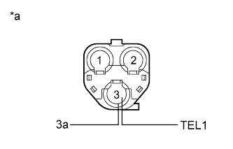 |
Disconnect the telephone and GPS antenna assembly connector from the telephone and GPS antenna cord (No. 2 floor wire).
Measure the resistance according to the value(s) in the table below.
| Tester Connection | Condition | Specified Condition |
| 3 (TEL1) - 3a | Always | 4 to 11 kΩ |
| *a | Telephone and GPS Antenna Assembly |
|
| ||||
| OK | |
|
| 3.INSPECT TELEPHONE AND GPS ANTENNA CORD (NO. 2 FLOOR WIRE) |
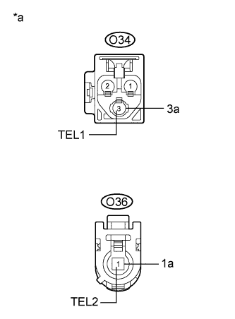 |
Disconnect the telephone and GPS antenna cord (No. 2 floor wire) connector from the DCM (Telematics Transceiver).
Measure the resistance according to the value(s) in the table below.
| Tester Connection | Condition | Specified Condition |
| O34-3 (TEL1) - O36-1 (TEL2) | Always | Below 1 Ω |
| O34-3a - O36-1a | Always | Below 1 Ω |
| O34-3 (TEL1) - Body ground | Always | 10 kΩ or higher |
| O34-3a - Body ground | Always | 10 kΩ or higher |
| *a | Telephone and GPS antenna cord (No. 2 Floor Wire) |
|
| ||||
| OK | |
|
| 4.REPLACE TELEPHONE AND GPS ANTENNA ASSEMBLY |
Replace the telephone and GPS antenna assembly with a known good one and check if the same problem occurs again (Click here).
|
| ||||
| OK | ||
 | ||
| ||
| 5.REPLACE DCM (TELEMATICS TRANSCEIVER) |
Replace the DCM (Telematics Transceiver) (Click here).
| NEXT | ||
| ||
| ||
