POWER ASSIST SYSTEMS POWER STEERING SYSTEM DETAILS STEERING COLUMN ASSEMBLY
CONSTRUCTION
The steering column assembly consists of an electric power steering column sub-assembly, power steering motor assembly and power steering ECU assembly.
The electrical power steering column sub-assembly includes a torque sensor and reduction mechanism.
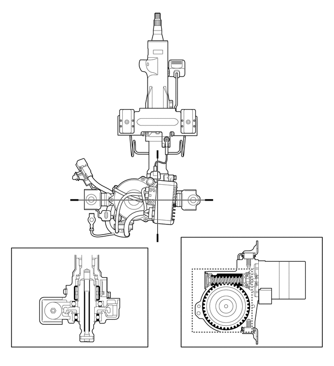
| *1 | Electrical Power Steering Column Sub-assembly | *2 | Power Steering ECU Assembly |
| *3 | Power Steering Motor Assembly | *4 | Torque Sensor |
| *5 | Reduction Mechanism | - | - |
| *a | A-A Cross Section | *b | B-B Cross Section |
The torque sensor consists of a sleeve, stub shaft and 2 detection coils.
The sleeve is mounted on the input shaft, and the stub shaft is mounted on the output shaft. The input shaft and the output shaft are joined by the torsion bar. The detection coils are placed on the outside of the sleeve to complete an excitation circuit without making contact.
When the steering wheel is turned, the twist that is created in the torsion bar creates a relative displacement between the sleeve and the stub shaft. The torque sensor outputs this change as an electrical signal to the power steering ECU assembly.
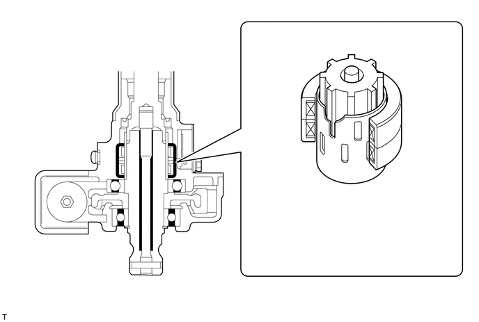
| *1 | Torque Sensor | *2 | Stub Shaft |
| *3 | Sleeve | *4 | Detection Coil |
| *5 | Input Shaft | *6 | Torsion Bar |
| *7 | Output Shaft | - | - |
A low inertia, low noise, and high power output brushless type power steering motor assembly is used.
The power steering motor assembly consists of a rotor, stator, motor shaft and rotation angle sensor.
The rotation angle sensor consists of a highly reliable and durable resolver sensor. The rotation angle sensor detects the rotation angle of the motor and outputs it to the power steering ECU assembly. As a result, it ensures efficient EPS control.
The torque that is generated by the power steering motor assembly is transmitted via the joint to the reduction mechanism.
The reduction mechanism reduces the speed of the power steering motor assembly via the worm gear and the wheel gear, and transmits it to the column shaft.
The wheel gear is made of a high strength, low friction, and low wear plastic material, to realize low noise and a lightweight construction.
A worm gear supported by ball bearings is used. Also, a spring is provided to ensure optimal gear engagement at all times.
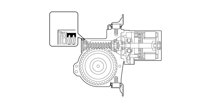
| *1 | Spring | *2 | Ball Bearing |
| *3 | Worm Gear | *4 | Rotation Angle Sensor |
| *5 | Rotor | *6 | Column Shaft |
| *7 | Wheel Gear | *8 | Motor Shaft |
| *9 | Stator | - | - |
| *a | This illustration is an example only. | - | - |