LIGHTING (EXT) LIGHTING SYSTEM CONTROL AUTOMATIC HIGH BEAM
FUNCTION OF MAIN COMPONENTS
| Component | Function | |
|---|---|---|
| Inner Rear View Mirror Assembly | Automatic High Beam Sensor | The automatic high beam sensor determines when to turn the high beams on and off after identifying the lights of oncoming vehicles, preceding vehicles and other lights from the picture information of its camera sensor. Then, it sends high beam request signals to the headlight swivel ECU assembly via Local Interconnect Network (LIN). |
| Headlight Swivel ECU Assembly | ·
The headlight swivel ECU assembly uses LIN communication (for automatic high beam actuation). ·
The headlight swivel ECU assembly acts as the gateway between the automatic high beam sensor and the CAN system. |
|
| Main Body ECU (Multiplex Network Body ECU) | ·
The main body ECU (multiplex network body ECU) receives an AUTO position signal and high beam position signal from headlight dimmer switch. ·
The main body ECU (multiplex network body ECU) receives high beam request signals from the mirror and transmits a signal to the power distributor. |
|
| Skid Control ECU | The skid control ECU outputs information about the average speed of the 4 wheels. This information is used by the automatic high beam sensor to control switching between the high and low beams of the automatic high beam system. | |
| ECM | The ECM outputs a signal to indicate that the shift lever is in R. Based on this signal, the automatic high beam sensor determines the direction of vehicle movement. | |
| Headlight Dimmer Switch Assembly | The headlight dimmer switch assembly transmits an AUTO position or high beam position signal to the main body ECU (multiplex network body ECU). | |
| Automatic Light Control Sensor | The automatic light control sensor detects the ambient light level and transmits a signal to the main body ECU (multiplex network body ECU). | |
| Combination Meter Assembly | Automatic High Beam Indicator Light | ·
The automatic high beam indicator light (yellow) illuminates to inform the driver when malfunctions are detected in this system. ·
The automatic high beam indicator light (green) illuminates to inform the driver when the automatic high beam system is activated. |
| Headlight High Beam Indicator Light | The headlight high beam indicator light illuminates to inform the driver when the high beams are on. | |
FUNCTION
When passing an oncoming vehicle:
The automatic high beam system turns off the high beams before an oncoming vehicle comes within approximately 800 m (2625 ft.).
When an oncoming vehicle passes out of camera sensor range, the automatic high beam system turns the high beams on after a short delay.
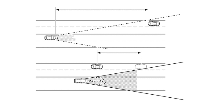
- HINT:
- ·
The detection distance varies depending on detected objects.
·The timing of turning on and off the high beams varies depending on the intensity of oncoming (and preceding) vehicle lights.
When passing a preceding vehicle:
When approaching a preceding vehicle, the automatic high beam system turns off the high beams approximately 600 m (1969 ft.) before reaching it.
When a preceding vehicle passes out of camera sensor range, the automatic high beam system turns the high beams on after a short delay.
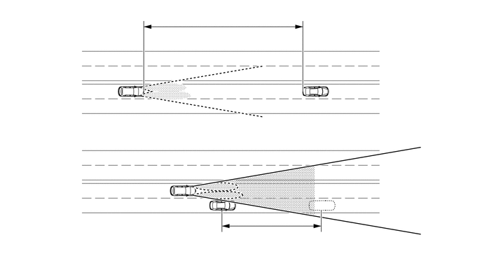
- HINT:
-
The timing of turning on and off the high beams varies depending on the intensity of the preceding vehicle lights.
DIAGNOSIS
When the headlight swivel ECU assembly or main body ECU (multiplex network body ECU) detects malfunctions in the automatic high beam system, Diagnostic Trouble Codes (DTCs) are stored in memory.
The DTCs can be read using the intelligent tester. For details, refer to the Repair Manual.