2GR-FE ENGINE CONTROL SFI SYSTEM TERMINALS OF ECM
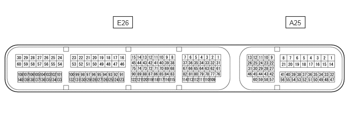
- HINT:
-
The standard voltage between each pair of the ECM terminals is shown in the table below. The appropriate conditions for checking each pair of the terminals are also indicated.
-
The result of checks should be compared with the standard voltage for that pair of terminals, and displayed in the "Specified Condition" column.
-
The illustration above can be used as a reference to identify the ECM terminal locations.
| Terminal No. (Symbol) | Wiring Color | Terminal Description | Condition | Specified Condition |
|---|---|---|---|---|
| A25-1 (BATT) - E26-49 (E1) | GR - BR | Battery (for measuring the battery voltage and for the ECM memory) | Always | 11 to 14 V |
| A25-2 (+B) - E26-49 (E1) | P - BR | Power source of ECM | Ignition switch ON | 11 to 14 V |
| A25-3 (+B2) - E26-49 (E1) | LG - BR | Power source of ECM | Ignition switch ON | 11 to 14 V |
| E26-60 (+BM) - E26-49 (E1) | R - BR | Power source of throttle actuator | Always | 11 to 14 V |
| A25-46 (MREL) - E26-49 (E1) | BE - BR | EFI MAIN relay operation signal | Ignition switch ON | 11 to 14 V |
| E26-111 (VCV1) - E26-49 (E1) | LG - BR | Power source for sensors (specific voltage) | Ignition switch ON | 4.5 to 5.5 V |
| A25-32 (IGSW) - E26-49 (E1) | V - BR | Ignition switch signal | Ignition switch ON | 11 to 14 V |
| A25-51 (STP) - E26-49 (E1) | BE - BR | Stop light switch assembly signal | Brake pedal depressed | 7.5 to 14 V |
| Brake pedal released | Below 1.5 V | |||
| A25-36 (ST1-) - E26-49 (E1) | GR - BR | Stop light switch assembly signal (opposite to STP terminal) | Ignition switch ON, brake pedal depressed | Below 1.5 V |
| Ignition switch ON, brake pedal released | 7.5 to 14 V | |||
| A25-56 (VCPA) - A25-55 (EPA) | P - Y | Power source of accelerator pedal position sensor (for VPA) | Ignition switch ON | 4.5 to 5.5 V |
| A25-59 (VCP2) - A25-58 (EPA2) | L - BE | Power source of accelerator pedal position sensor (for VPA2) | Ignition switch ON | 4.5 to 5.5 V |
| A25-54 (VPA) - A25-55 (EPA) | G - Y | Accelerator pedal position sensor signal (for engine control) | Ignition switch ON, accelerator pedal fully released | 0.5 to 1.1 V |
| Ignition switch ON, accelerator pedal fully depressed | 2.6 to 4.5 V | |||
| A25-57 (VPA2) - A25-58 (EPA2) | R - BE | Accelerator pedal position sensor signal (for sensor malfunction detection) | Ignition switch ON, accelerator pedal fully released | 1.2 to 2.0 V |
| Ignition switch ON, accelerator pedal fully depressed | 3.4 to 5.0 V | |||
| E26-126 (VCTA) - E26-125 (ETA) | B - R | Power source for throttle position sensor (specific voltage) | Ignition switch ON | 4.5 to 5.5 V |
| E26-128 (VTA1) - E26-125 (ETA) | Y - R | Throttle position sensor signal (for engine control) | Ignition switch ON, accelerator pedal fully released | 0.5 to 1.1 V |
| Ignition switch ON, accelerator pedal fully depressed | 3.2 to 4.8 V | |||
| E26-127 (VTA2) - E26-125 (ETA) | W - R | Throttle position sensor signal (for sensor malfunction detection) | Ignition switch ON, accelerator pedal fully released | 2.1 to 3.1 V |
| Ignition switch ON, accelerator pedal fully depressed | 4.6 to 5.0 V | |||
| A25-45 (TC) - E26-49 (E1) | P - BR | Terminal TC of DLC3 | Ignition switch ON | 11 to 14 V |
| A25-23 (TACH) - E26-49 (E1) | B - BR | Engine speed signal (for combination meter assembly) | Idling | Pulse generation
(see waveform 1) |
| A25-10 (SPD) - E26-49 (E1) | L - BR | Vehicle speed signal from combination meter assembly | Driving at 20 km/h (12 mph) | Pulse generation
(see waveform 2) |
| A25-27 (W) - E26-49 (E1) | LG - BR | Malfunction Indicator Lamp (MIL) operation signal | Ignition switch ON
(MIL goes on) |
Below 3.0 V |
| Idling | 11 to 14 V | |||
| E26-58 (#10) - E26-25 (E01) | B - W-B | No. 1 fuel injector assembly signal | Ignition switch ON | 11 to 14 V |
| Idling | Pulse generation
(see waveform 3) |
|||
| E26-54 (#20) - E26-25 (E01) | R - W-B | No. 2 fuel injector assembly signal | Ignition switch ON | 11 to 14 V |
| Idling | Pulse generation
(see waveform 3) |
|||
| E26-57 (#30) - E26-25 (E01) | Y - W-B | No. 3 fuel injector assembly signal | Ignition switch ON | 11 to 14 V |
| Idling | Pulse generation
(see waveform 3) |
|||
| E26-53 (#40) - E26-25 (E01) | L - W-B | No. 4 fuel injector assembly signal | Ignition switch ON | 11 to 14 V |
| Idling | Pulse generation
(see waveform 3) |
|||
| E26-56 (#50) - E26-25 (E01) | P - W-B | No. 5 fuel injector assembly signal | Ignition switch ON | 11 to 14 V |
| Idling | Pulse generation
(see waveform 3) |
|||
| E26-55 (#60) - E26-25 (E01) | G - W-B | No. 6 fuel injector assembly signal | Ignition switch ON | 11 to 14 V |
| Idling | Pulse generation
(see waveform 3) |
|||
| A25-9 (STA) - E26-49 (E1) | LG - BR | ST relay operation signal | Cranking | 11 to 14 V |
| E26-35 (OC1+) - E26-5 (OC1-) | W - B | Camshaft timing oil control valve assembly (for intake camshaft of bank 1) operation signal | Idling | Pulse generation
(see waveform 4) |
| E26-34 (OC2+) - E26-4 (OC2-) | GR - R | Camshaft timing oil control valve assembly (for intake camshaft of bank 2) operation signal | Idling | Pulse generation
(see waveform 4) |
| E26-33 (OE1+) - E26-3 (OE1-) | L - LG | Camshaft timing oil control valve assembly (for exhaust camshaft of bank 1) operation signal | Idling | Pulse generation
(see waveform 5) |
| E26-32 (OE2+) - E26-2 (OE2-) | W - Y | Camshaft timing oil control valve assembly (for exhaust camshaft of bank 2) operation signal | Idling | Pulse generation
(see waveform 5) |
| E26-81 (VV1+) - E26-110 (VV1-) | L - P | VVT sensor (for intake camshaft of bank 1) signal | Idling | Pulse generation
(see waveform 6) |
| E26-78 (VV2+) - E26-110 (VV1-) | W - P | VVT sensor (for intake camshaft of bank 2) signal | Idling | Pulse generation
(see waveform 6) |
| E26-79 (EV1+) - E26-110 (VV1-) | V - P | VVT sensor (for exhaust camshaft of bank 1) signal | Idling | Pulse generation
(see waveform 7) |
| E26-80 (EV2+) - E26-110 (VV1-) | G - P | VVT sensor (for exhaust camshaft of bank 2) signal | Idling | Pulse generation
(see waveform 7) |
| E26-76 (NE+) - E26-109 (NE-) | G - R | Crankshaft position sensor signal | Idling | Pulse generation
(see waveform 6, 7) |
| A25-22 (NEO)*2 - E26-49 (E1) | G - BR | Crankshaft position sensor signal sent to certification ECU (smart key ECU assembly) | Idling with warm engine | Pulse generation (see waveform 8) |
| E26-30 (M+) - E26-59 (ME01) | W - W-B | Throttle actuator operation signal (positive terminal) | Idling with warm engine | Pulse generation
(see waveform 9) |
| E26-29 (M-) - E26-59 (ME01) | B - W-B | Throttle actuator operation signal (negative terminal) | Idling with warm engine | Pulse generation
(see waveform 10) |
| E26-107 (IGT1) - E26-49 (E1) | W - BR | No. 1 ignition coil assembly (ignition signal) | Idling | Pulse generation
(see waveform 11) |
| E26-140 (IGT2) - E26-49 (E1) | G - BR | No. 2 ignition coil assembly (ignition signal) | Idling | Pulse generation
(see waveform 11) |
| E26-106 (IGT3) - E26-49 (E1) | G - BR | No. 3 ignition coil assembly (ignition signal) | Idling | Pulse generation
(see waveform 11) |
| E26-139 (IGT4) - E26-49 (E1) | LG - BR | No. 4 ignition coil assembly (ignition signal) | Idling | Pulse generation
(see waveform 11) |
| E26-105 (IGT5) - E26-49 (E1) | P - BR | No. 5 ignition coil assembly (ignition signal) | Idling | Pulse generation
(see waveform 11) |
| E26-138 (IGT6) - E26-49 (E1) | L - BR | No. 6 ignition coil assembly (ignition signal) | Idling | Pulse generation
(see waveform 11) |
| E26-103 (IGF1) - E26-49 (E1) | V - BR | Ignition coil assembly (ignition confirmation signal) | Ignition switch ON | 4.5 to 5.0 V |
| Idling | Pulse generation
(see waveform 11) |
|||
| E26-114 (THW) - E26-117 (ETHW) | B - P | Engine coolant temperature sensor signal | Idling, engine coolant temperature 60 to 120°C (140 to 248°F) | 0.2 to 1.0 V |
| E26-96 (THA) - E26-118 (ETHA) | P - Y | Intake air temperature sensor signal | Idling, intake air temperature 0 to 80°C (32 to 176°F) | 0.5 to 3.4 V |
| E26-46 (AICV) - E26-49 (E1) | L - BR | Vacuum switching valve (for air intake control valve) operation signal | Ignition switch ON | 11 to 14 V |
| E26-98 (VG) - E26-130 (E2G) | L - B | Mass air flow meter sub-assembly signal | Idling, shift lever in P or N, A/C switch off | 0.5 to 3.0 V |
| E26-47 (ACIS) - E26-49 (E1) | L - BR | Intake air control valve assembly (for acoustic control induction system) operation signal | Ignition switch ON | 11 to 14 V |
| E26-48 (PRG) - E26-49 (E1) | R - BR | Purge VSV operation signal | Ignition switch ON | 11 to 14 V |
| Idling with warm engine | Pulse generation
(see waveform 12) |
|||
| E26-100 (A1A+) - E26-49 (E1) | L - BR | Air fuel ratio sensor (bank 1 sensor 1) signal | Ignition switch ON | 3.3 V*1 |
| E26-132 (A1A-) - E26-49 (E1) | P - BR | Air fuel ratio sensor (bank 1 sensor 1) signal | Ignition switch ON | 2.9 V*1 |
| E26-99 (A2A+) - E26-49 (E1) | R - BR | Air fuel ratio sensor (bank 2 sensor 1) signal | Ignition switch ON | 3.3 V*1 |
| E26-131 (A2A-) - E26-49 (E1) | G - BR | Air fuel ratio sensor (bank 2 sensor 1) signal | Ignition switch ON | 2.9 V*1 |
| E26-26 (HA1A) - E26-21 (E05) | R - W-B | Air fuel ratio sensor (bank 1 sensor 1) heater operation signal | Idling | Pulse generation (see waveform 13) |
| Ignition switch ON | 11 to 14 V | |||
| E26-20 (HA2A) - E26-21 (E05) | W - W-B | Air fuel ratio sensor (bank 2 sensor 1) heater operation signal | Idling | Pulse generation (see waveform 13) |
| Ignition switch ON | 11 to 14 V | |||
| E26-101 (OX1B) - E26-102 (EX1B) | W - GR | Heated oxygen sensor (bank 1 sensor 2) signal | Engine speed maintained at 2500 rpm for 2 minutes after warming up engine | Pulse generation
(see waveform 14) |
| E26-133 (OX2B) - E26-134 (EX2B) | B - R | Heated oxygen sensor (bank 2 sensor 2) signal | Engine speed maintained at 2500 rpm for 2 minutes after warming up engine | Pulse generation
(see waveform 14) |
| E26-28 (HT1B) - E26-27 (E04) | G - W-B | Heated oxygen sensor (bank 1 sensor 2) heater operation signal | Idling | Below 3.0 V |
| Ignition switch ON | 11 to 14 V | |||
| E26-22 (HT2B) - E26-27 (E04) | Y - W-B | Heated oxygen sensor (bank 2 sensor 2) heater operation signal | Idling | Below 3.0 V |
| Ignition switch ON | 11 to 14 V | |||
| A25-8 (ACM) - E26-49 (E1) | R - BR | Vacuum switching valve (for active control engine mount system) operation signal | Ignition switch ON | 11 to 14 V |
| E26-65 (NSW) - E26-49 (E1) | LG - BR | Park/Neutral position switch assembly signal | Ignition switch ON and shift lever in P or N | Below 3.0 V |
| Ignition switch ON and shift lever not in P or N | 11 to 14 V | |||
| E26-83 (KNK1) - E26-115 (EKNK) | R - G | Knock control sensor (bank 1) signal | Engine speed maintained at 4000 rpm after warming up engine | Pulse generation
(see waveform 15) |
| E26-84 (KNK2) - E26-116 (EKN2) | B - W | Knock control sensor (bank 2) signal | Engine speed maintained at 4000 rpm after warming up engine | Pulse generation
(see waveform 15) |
| E26-70 (P) - E26-49 (E1) | B - BR | P shift position switch signal | Ignition switch ON and shift lever in P | 11 to 14 V |
| Ignition switch ON and shift lever not in P | Below 1 V | |||
| E26-68 (R) - E26-49 (E1) | GR - BR | R shift position switch signal | Ignition switch ON and shift lever in R | 11 to 14 V |
| Ignition switch ON and shift lever not in R | Below 1 V | |||
| E26-71 (N) - E26-49 (E1) | L - BR | N shift position switch signal | Ignition switch ON and shift lever in N | 11 to 14 V |
| Ignition switch ON and shift lever not in N | Below 1 V | |||
| E26-69 (D) - E26-49 (E1) | G - BR | D shift position switch signal | Ignition switch ON and shift lever in D or S | 11 to 14 V |
| Ignition switch ON and shift lever not in D or S | Below 1 V | |||
| A25-37 (S) - E26-49 (E1) | G - BR | S shift position switch signal | Ignition switch ON and shift lever in S | 11 to 14 V |
| Ignition switch ON and shift lever not in S | Below 1 V | |||
| A25-50 (SFTD) - E26-49 (E1) | V - BR | Down shift switch signal | Ignition switch ON and shift lever in S | 11 to 14 V |
| Ignition switch ON and shift lever in "-" (down shift) selected | Below 1 V | |||
| A25-34 (SFTU) - E26-49 (E1) | R - BR | Up shift switch signal | Ignition switch ON and shift lever in S | 11 to 14 V |
| Ignition switch ON and shift lever in "+" (up shift) selected | Below 1 V | |||
| A25-18 (FPC) - E26-49 (E1) | W - BR | Fuel pump control | Engine stopped, ignition switch ON | Below 1.5 V |
| A25-13 (CANH) - E26-49 (E1) | B - BR | CAN communication line | Ignition switch ON | Pulse generation
(see waveform 16) |
| A25-26 (CANL) - E26-49 (E1) | W - BR | CAN communication line | Ignition switch ON | Pulse generation
(see waveform 17) |
| E26-31 (CAN+) - E26-49 (E1) | B - BR | CAN communication line | Ignition switch ON | Pulse generation
(see waveform 16) |
| E26-1 (CAN-) - E26-49 (E1) | Y - BR | CAN communication line | Ignition switch ON | Pulse generation
(see waveform 17) |
| E26-112 (ALT) - E26-49 (E1) | L - BR | Generator assembly | Ignition switch ON | 11 to 14 V |
| A25-5 (RFC) - E26-49 (E1) | G - BR | Cooling fan control | Ignition switch ON, A/C switch on (max cool) | Pulse generation
(see waveform 18) |
| E26-108 (GE01) - E26-49 (E1) | G - BR | Shielded earth (ground) circuit of throttle actuator | Always | Below 1 Ω |
| A25-14 (EC) - Body ground | W-B - - | Ground | Always | Below 1 Ω |
| E26-49 (E1) - Body ground | BR - - | Ground | Always | Below 1 Ω |
| E26-25 (E01) - Body ground | W-B - - | Ground | Always | Below 1 Ω |
| E26-24 (E02) - Body ground | W-B - - | Earth (ground) circuit of ECM | Always | Below 1 Ω |
| E26-27 (E04) - Body ground | W-B - - | Ground | Always | Below 1 Ω |
| E26-21 (E05) - Body ground | W-B - - | Ground | Always | Below 1 Ω |
*1: The ECM terminal voltage is constant regardless of the output voltage from the sensor.
*2: w/ smart entry and start system.
WAVEFORM 1
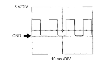
| ECM Terminal Name | Between TACH and E1 |
| Tester Range | 5 V/DIV., 10 ms./DIV. |
| Condition | Idling |
- HINT:
-
The wavelength becomes shorter as the engine speed increases.
WAVEFORM 2
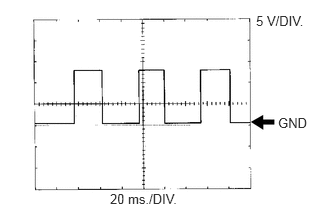
| ECM Terminal Name | Between SPD and E1 |
| Tester Range | 5 V/DIV., 20 ms./DIV. |
| Condition | Driving at 20 km/h (12 mph) |
- HINT:
-
The wavelength becomes shorter as the vehicle speed increases.
WAVEFORM 3
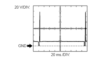
| ECM Terminal Name | Between #10 (to #60) and E01 |
| Tester Range | 20 V/DIV., 20 ms./DIV. |
| Condition | Idling |
- HINT:
-
The wavelength becomes shorter as the engine speed increases.
WAVEFORM 4
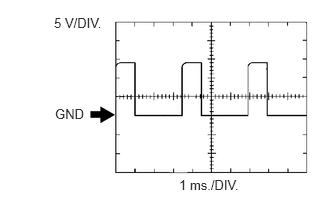
| ECM Terminal Name | Between OC1+ and OC1-, or OC2+ and OC2- |
| Tester Range | 5 V/DIV., 1 ms./DIV. |
| Condition | Idling |
WAVEFORM 5
| ECM Terminal Name | Between OE1+ and OE1-, or OE2+ and OE2- |
| Tester Range | 5 V/DIV., 1 ms./DIV. |
| Condition | Idling |
WAVEFORM 6
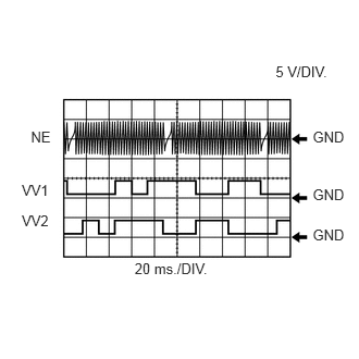
| ECM Terminal Name | Between NE+ and NE-
Between VV1+ and VV1- Between VV2+ and VV1- |
| Tester Range | 5 V/DIV., 20 ms./DIV. |
| Condition | Idling |
- HINT:
-
The wavelength becomes shorter as the engine speed increases.
WAVEFORM 7
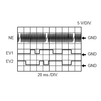
| ECM Terminal Name | Between NE+ and NE-
Between EV1+ and VV1- Between EV2+ and VV1- |
| Tester Range | 5 V/DIV., 20 ms./DIV. |
| Condition | Idling |
- HINT:
-
The wavelength becomes shorter as the engine speed increases.
WAVEFORM 8
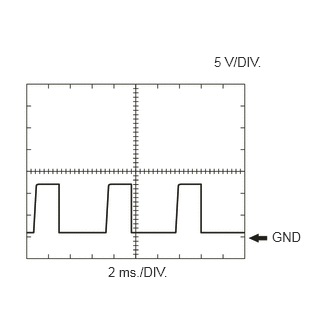
| ECM Terminal Name | Between NEO and E1 |
| Tester Range | 5 V/DIV., 2 ms./DIV. |
| Condition | Idling with warm engine |
- HINT:
-
The wavelength becomes shorter as the engine speed increases.
WAVEFORM 9
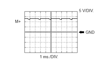
| ECM Terminal Name | Between M+ and ME01 |
| Tester Range | 5 V/DIV., 1 ms./DIV. |
| Condition | Idling with warm engine |
- HINT:
-
The duty ratio varies depending on the throttle actuator operation.
WAVEFORM 10
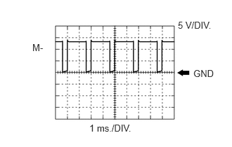
| ECM Terminal Name | Between M- and ME01 |
| Tester Range | 5 V/DIV., 1 ms./DIV. |
| Condition | Idling with warm engine |
- HINT:
-
The duty ratio varies depending on the throttle actuator operation.
WAVEFORM 11
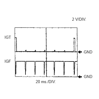
| ECM Terminal Name | Between IGT (1 to 6) and E1
Between IGF1 and E1 |
| Tester Range | 2 V/DIV., 20 ms./DIV. |
| Condition | Idling |
- HINT:
-
The wavelength becomes shorter as the engine speed increases.
WAVEFORM 12
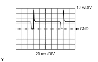
| ECM Terminal Name | Between PRG and E1 |
| Tester Range | 10 V/DIV., 20 ms./DIV. |
| Condition | Idling with warm engine |
- HINT:
-
If the waveform is not similar to the illustration, check the waveform again after idling for 10 minutes or more.
WAVEFORM 13
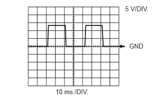
| ECM Terminal Name | Between HA1A and E05, or HA2A and E05 |
| Tester Range | 5 V/DIV., 10 ms./DIV. |
| Condition | Idling |
- HINT:
-
The wavelength varies in accordance with the engine operating condition.
WAVEFORM 14
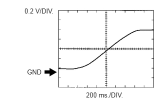
| ECM Terminal Name | Between OX1B and EX1B, or OX2B and EX2B |
| Tester Range | 0.2 V/DIV., 200 ms./DIV. |
| Condition | Engine speed maintained at 2500 rpm for 2 minutes after warming up engine |
- HINT:
-
In the Data List, item O2S B1S2 and O2S B2S2 shows the ECM values from the heated oxygen sensor.
WAVEFORM 15
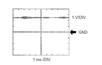
| ECM Terminal Name | Between KNK1 and EKNK, or KNK2 and EKN2 |
| Tester Range | 1 V/DIV., 1 ms./DIV. |
| Condition | Engine speed maintained at 4000 rpm after warming up engine |
- HINT:
- ·
The wavelength becomes shorter as the engine speed increases.
·The waveforms and amplitudes displayed differ slightly depending on the vehicle condition.
WAVEFORM 16
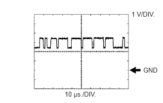
| ECM Terminal Name | Between CANH and E1, or CAN+ and E1 |
| Tester Range | 1 V/DIV., 10 μs./DIV. |
| Condition | Ignition switch ON |
- HINT:
-
The waveform varies depending on the CAN communication signal.
WAVEFORM 17
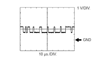
| ECM Terminal Name | Between CANL and E1, or CAN- and E1 |
| Tester Range | 1 V/DIV., 10 μs./DIV. |
| Condition | Ignition switch ON |
- HINT:
-
The waveform varies depending on the CAN communication signal.
WAVEFORM 18
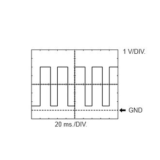
| ECM Terminal Name | Between RFC and E1 |
| Tester Range | 1 V/DIV., 20 ms./DIV. |
| Condition | Ignition switch ON, A/C switch on (max cool) |
- HINT:
-
The wavelength becomes shorter as the engine coolant temperature.