2GR-FE ENGINE MECHANICAL CYLINDER HEAD DISASSEMBLY
CAUTION / NOTICE / HINT
- HINT:
- ·
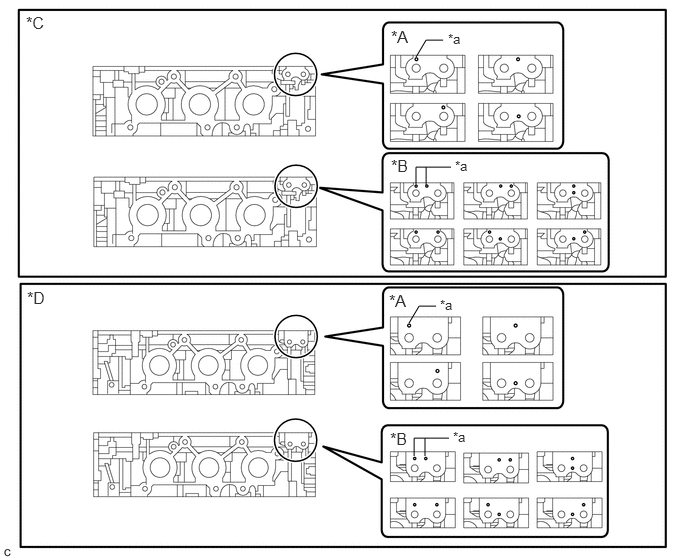
Select the No. 1 valve rocker arm sub-assemblies, inner compression springs and valve spring retainers based on the identification mark on the cylinder head.
 4.333,0.594 4.438,0.417 4.438,0.417 4.615,0.417 false 4.333,1.917 4.333,1.74 4.333,1.74 4.698,1.74 false 4.438,1.927 4.438,1.74 false 4.313,4.75 4.313,4.563 4.313,4.563 4.677,4.563 false 4.427,4.75 4.427,4.563 false 4.26,3.365 4.365,3.188 4.365,3.188 4.542,3.188 false 4.073,0.281 4.385,0.531 0.313,0.25 12 false *A 4.073,1.625 4.479,1.906 0.406,0.281 12 false *B 0.271,0.135 0.688,0.417 0.417,0.281 12 false *C 0.281,3 0.729,3.281 0.448,0.281 12 false *D 4.052,3.031 4.365,3.281 0.313,0.25 12 false *A 4.063,4.469 4.469,4.75 0.406,0.281 12 false *B 4.667,0.323 4.979,0.521 0.313,0.198 10 false *a 4.74,1.646 5.052,1.844 0.313,0.198 10 false *a 4.719,4.469 5.031,4.667 0.313,0.198 10 false *a 4.583,3.094 4.896,3.292 0.313,0.198 10 false *a
*A Type A *B Type B *C Cylinder Head RH *D Cylinder Head LH *a Identification Mark - -
Type Identification Mark Compression Spring Shape A 1 Hole Straight B 2 Holes Taper
· 0.052,0.083 1.708,4.49 1.656,4.406 1.771,0.073 3.396,4.479 1.625,4.406 1.156,2.323 1.156,2.094 false 2.823,2.313 2.823,2.083 false 1.208,2.99 0.885,2.99 false 2.917,3.01 2.594,3.01 false 1.26,3.938 0.938,3.938 false 2.979,3.979 2.646,3.979 false 0.094,0.104 0.438,0.333 0.344,0.229 12 false *A 1.813,0.094 2.188,0.375 0.375,0.281 12 false *B 1.094,2.375 1.406,2.531 0.313,0.156 10 false *1 1.271,2.917 1.583,3.073 0.313,0.156 10 false *2 1.313,3.875 1.625,4.031 0.313,0.156 10 false *3 0.635,2.49 0.948,2.646 0.313,0.156 10 false *a 1.417,0.917 1.646,1.125 0.229,0.208 10 false *b 3.125,0.906 3.354,1.115 0.229,0.208 10 false *b 2.354,2.479 2.667,2.635 0.313,0.156 10 false *a 2.76,2.354 3.073,2.51 0.313,0.156 10 false *1 2.979,2.927 3.292,3.083 0.313,0.156 10 false *2 3.031,3.917 3.344,4.073 0.313,0.156 10 false *3
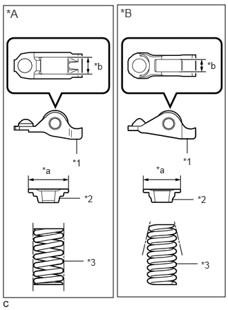
*A Type A *B Type B *1 No. 1 Valve Rocker Arm Sub-assembly *2 Valve Spring Retainer *3 Inner Compression Spring *a Valve Spring Retainer Diameter *b No. 1 Valve Rocker Arm Sub-assembly Roller Width
There are 2 types of No. 1 valve rocker arms, inner compression springs and valve spring retainers. The 2 types are not interchangeable.
Type No. 1 ValveRocker Arm Sub-assembly Roller Width Valve Spring Retainer Diameter Compression Spring Shape A 10.7 mm (0.421 in.) 23.4 mm (0.921 in.) Straight B 8.0 mm (0.315 in.) 18.9 mm (0.7441 in.) Taper
PROCEDURE

 13716
1.REMOVE VALVE STEM CAP
Remove the valve stem caps from the cylinder heads.
- HINT:
-
Arrange the removed parts in the correct order.
13711
2.REMOVE INTAKE VALVE
- HINT:
-
Type A and Type B can be distinguished by the shape of the compression spring.
| *A | Type A |
| *B | Type B |
| *1 | No. 1 Valve Rocker Arm Sub-assembly |
| *2 | Valve Spring Retainer |
| *3 | Inner Compression Spring |
| *a | Valve Spring Retainer Diameter |
| *b | No. 1 Valve Rocker Arm Sub-assembly Roller Width |
| Type | No. 1 Valve Rocker Arm Sub-assembly Roller Width | Valve Spring Retainer Diameter | Inner Compression Spring Shape |
|---|---|---|---|
| A | 10.7 mm (0.421 in.) | 23.4 mm (0.921 in.) | Straight |
| B | 8.0 mm (0.315 in.) | 18.9 mm (0.744 in.) | Taper |
Type A:
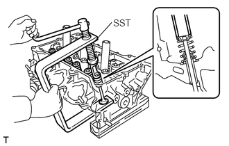
Using SST, compress the inner compression spring and remove the valve spring retainer locks.
- SST
- 09202-70020 (09202-00010, 09202-01010, 09202-01020)
Type B:
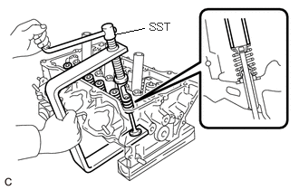
Using SST, compress the inner compression spring and remove the valve spring retainer locks.
- SST
- 09202-70020 (09202-01010, 09202-01020)
09202-00020
Remove the valve spring retainer, inner compression spring and intake valve.
- HINT:
-
Arrange the removed parts in the correct order.
13715
3.REMOVE EXHAUST VALVE
- HINT:
-
Type A and Type B can be distinguished by the shape of the compression spring.
| *A | Type A |
| *B | Type B |
| *1 | No. 1 Valve Rocker Arm Sub-assembly |
| *2 | Valve Spring Retainer |
| *3 | Inner Compression Spring |
| *a | Valve Spring Retainer Diameter |
| *b | No. 1 Valve Rocker Arm Sub-assembly Roller Width |
| Type | No. 1 Valve Rocker Arm Sub-assembly Roller Width | Valve Spring Retainer Diameter | Inner Compression Spring Shape |
|---|---|---|---|
| A | 10.7 mm (0.421 in.) | 23.4 mm (0.921 in.) | Straight |
| B | 8.0 mm (0.315 in.) | 18.9 mm (0.744 in.) | Taper |
Type A:
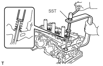
Using SST, compress the inner compression spring and remove the valve spring retainer locks.
- SST
- 09202-70020 (09202-00010, 09202-01010, 09202-01020)
Type B:
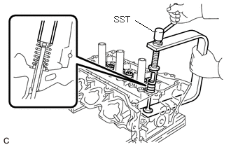
Using SST, compress the inner compression spring and remove the valve spring retainer locks.
- SST
- 09202-70020 (09202-01010, 09202-01020)
09202-00020
Remove the valve spring retainer, inner compression spring and exhaust valve.
- HINT:
-
Arrange the removed parts in the correct order.
13711E
4.REMOVE VALVE STEM OIL SEAL
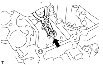
Using needle-nose pliers, remove the valve stem oil seals.
13734
5.REMOVE VALVE SPRING SEAT
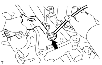
Using compressed air and a Magnet Hand, remove the valve spring seats by blowing air onto them.
11117E
6.REMOVE NO. 1 STRAIGHT SCREW PLUG
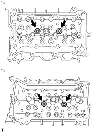
| *a | for Bank 1 |
| *b | for Bank 2 |
Using a 10 mm hexagon wrench, remove the 4 No. 1 straight screw plugs and 4 gaskets.
- NOTICE:
-
If water leaks from a straight screw plug or the plug is corroded, replace it.
11117F
7.REMOVE NO. 2 STRAIGHT SCREW PLUG
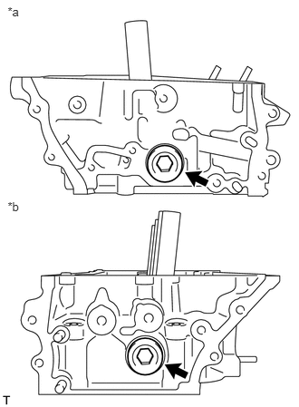
| *a | for Bank 1 |
| *b | for Bank 2 |
Using a 14 mm hexagon wrench, remove the 2 No. 2 straight screw plugs and 2 gaskets.
- NOTICE:
-
If water leaks from a straight screw plug or the plug is corroded, replace it.