RM2030EQ
_51
Engine / Hybrid System
_014636
2GR-FE FUEL
_0074425
FUEL SENDER GAUGE ASSEMBLY
G
2GR-FE FUEL FUEL SENDER GAUGE ASSEMBLY INSPECTION
PROCEDURE

 83320
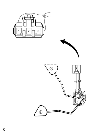
1.INSPECT FUEL SENDER GAUGE ASSEMBLY
a.
0.167,0.135 1.948,1.448
1.781,1.313
1.417,3.906 0.698,3.906
false
1.792,2.396 0.698,2.396
false
0.25,0.208 0.448,0.427
0.198,0.219
10
false
*a
0.542,2.313 0.688,2.49
0.146,0.177
10
false
F
0.552,3.833 0.698,4.01
0.146,0.177
10
false
E
| *a | Front view of wire harness connector
(to Fuel Sender Gauge Assembly) |
Check that the float moves smoothly between F and E.
b.
Measure the resistance between the terminals 1 and 2 of connector according to the value(s) in the table below.
- Standard Resistance:
Float Level Resistance (Ω) F 13.5 to 16.5 Between E and F 13.5 to 414.5 (Gradually changes) E 405.5 to 414.5
If the value is not as specified, replace the fuel sender gauge assembly.