Home › Audio / Visual / Telematics › PARK ASSIST / MONITORING › PARKING ASSIST MONITOR SYSTEM › 2012.02–2015.04
RM2030EQ _56 Audio / Visual / Telematics _014660 PARK ASSIST / MONITORING _0074557 PARKING ASSIST MONITOR SYSTEM U

PARK ASSIST / MONITORING  PARKING ASSIST MONITOR SYSTEM  TERMINALS OF ECU  


REAR TELEVISION CAMERA ASSEMBLY


a.

Disconnect the T6 connector from the rear television camera assembly.

E220918N10
3.406,0.104 3.802,0.344 0.396,0.24 3.531,0.135 3.802,0.365 0.271,0.229 10 false T6


b.

Measure the voltage of each terminal of the wire harness side connector.

Terminal No. (Symbol) Wiring Color Terminal Description Condition Specified Condition
T6-6 (CB+) - Body ground B - Body ground Power source Engine switch on (IG)
Shift lever in R
5.5 to 7.05 V

If the result is not as specified, there may be a malfunction on the wire harness side.


c.

Measure the resistance according to the value(s) in the table below.

Terminal No. (Symbol) Wiring Color Terminal Description Condition Specified Condition
T6-1 (CURT) - Body ground BR - Body ground Ground Always 10 kΩ or higher

If the result is not as specified, there may be a malfunction on the wire harness side.


d.

Reconnect the T6 connector to the rear television camera assembly.


e.

Check for pulses between each terminal of the connector.

Terminal No. (Symbol) Wiring Color Terminal Description Condition Specified Condition
T6-3 (CV+) - T6-2 (CV-) W - R Video signal Engine switch on (IG)
Shift lever in R
Camera lens not covered, displaying an image
Pulse generation
(See waveform 1)
Engine switch on (IG)
Shift lever in R
Camera lens covered, blacking out screen
Pulse generation
(See waveform 2)

HINT:

A waterproof connector is used for the rear television camera assembly. Therefore, inspect the waveform at the navigation ECU sub-assembly with the connector connected.


If the result is not as specified, the rear television camera assembly may have a malfunction.
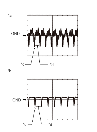

f.
E265838C05
0.896,2.281 1.094,2.281 1.094,2.281 1.219,1.708 false 0.979,4.417 1.125,4.417 1.125,4.417 1.24,3.844 false 1.698,2.292 1.417,2.292 1.417,2.292 1.323,1.615 false 1.698,4.396 1.469,4.396 1.469,4.396 1.354,3.781 false 0.281,0.458 0.594,0.656 0.313,0.198 10 *a 0.271,2.427 0.583,2.625 0.313,0.198 10 *b 0.74,2.188 1.052,2.385 0.313,0.198 10 *c 1.771,2.208 2.083,2.406 0.313,0.198 10 *d 0.813,4.323 1.125,4.521 0.313,0.198 10 *c 1.719,4.323 2.031,4.521 0.313,0.198 10 *d 0.438,3.458 0.906,3.771 0.469,0.313 10 GND 0.396,1.104 0.865,1.417 0.469,0.313 10 GND
*a Waveform 1 (camera lens not covered, displaying an image)
*b Waveform 2 (camera lens covered, blacking out the screen)
*c Synchronization Signal
*d Video Waveform


Reference (Oscilloscope waveform):

HINT:

A waterproof connector is used for the rear television camera assembly. Therefore, inspect the waveform at the navigation ECU sub-assembly with the connector connected.


i.

Waveform 1 (camera lens is not covered, displaying an image)

Item Content
Terminal No. (Symbol) T6-3 (CV+) - T6-2 (CV-)
Tool Setting 200 mV/DIV., 50 μsec./DIV.
Condition Engine switch on (IG), shift lever in R

HINT:

The video waveform changes according to the image sent by the rear television camera assembly.


ii.

Waveform 2 (camera lens is covered, blacking out the screen)

Item Content
Terminal No. (Symbol) T6-3 (CV+) - T6-2 (CV-)
Tool Setting 200 mV/DIV., 50 μsec./DIV.
Condition Engine switch on (IG), shift lever in R

HINT:

The video waveform changes according to the image sent by the rear television camera assembly.


INSTRUMENT PANEL JUNCTION BLOCK ASSEMBLY AND MAIN BODY ECU (MULTIPLEX NETWORK BODY ECU)
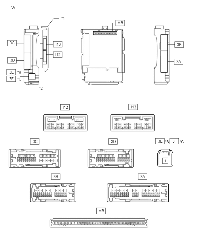

B278841C41
2.188,3.781 2.51,3.99 0.323,0.208 5.625,5.01 5.948,5.219 0.323,0.208 6.302,2.135 6.625,2.344 0.323,0.208 1.927,1.875 2.25,2.083 0.323,0.208 1.927,1.5 2.25,1.708 0.323,0.208 0.271,2.083 0.594,2.292 0.323,0.208 0.24,2.51 0.563,2.719 0.323,0.208 0.24,2.75 0.563,2.958 0.323,0.208 0.271,1.458 0.594,1.667 0.323,0.208 6.323,1.51 6.646,1.719 0.323,0.208 3.927,5.021 4.25,5.229 0.323,0.208 1.094,5.021 1.417,5.229 0.323,0.208 1.854,6.292 2.177,6.5 0.323,0.208 5,6.292 5.323,6.5 0.323,0.208 3.49,7.531 3.823,7.75 0.333,0.219 4.656,3.771 4.979,3.979 0.323,0.208 6.146,5.01 6.469,5.219 0.323,0.208 4.188,0.729 4.51,0.938 0.323,0.208 4.073,1.135 4.073,0.833 4.073,0.833 4.188,0.833 false 6.063,1.615 6.323,1.615 false 6.063,2.229 6.302,2.229 false 1.677,1.979 1.927,1.979 false 1.667,1.604 1.927,1.604 false 0.594,2.188 0.865,2.188 false 0.719,2.771 1.031,2.771 false 0.594,1.563 0.854,1.563 false 1.719,0.958 1.938,0.677 1.938,0.677 2.146,0.677 false 1.458,2.125 1.563,2.125 false 1.448,3.01 1.448,1.583 1.448,1.583 1.563,1.583 false 3.563,7.552 3.948,7.792 0.385,0.24 10 false MB 5.719,5.031 6.021,5.25 0.302,0.219 10 false 3E 1.188,5.042 1.469,5.281 0.281,0.24 10 false 3C 1.938,6.313 2.26,6.615 0.323,0.302 10 false 3B 5.083,6.313 5.385,6.542 0.302,0.229 10 false 3A 4.021,5.042 4.417,5.323 0.396,0.281 10 false 3D 4.74,3.792 5.073,4.125 0.333,0.333 10 false I13 2.271,3.802 2.573,3.99 0.302,0.188 10 false I12 6.385,2.146 6.656,2.385 0.271,0.24 10 false 3A 2,1.896 2.313,2.156 0.313,0.26 10 false I12 2.01,1.521 2.313,1.729 0.302,0.208 10 false I13 0.365,2.094 0.667,2.281 0.302,0.188 10 false 3D 0.333,2.531 0.615,2.771 0.281,0.24 10 false 3E 0.625,2.542 1,2.885 0.375,0.344 10 false *B 0.333,2.771 0.594,2.969 0.26,0.198 10 false 3F 0.625,2.781 1.01,3.125 0.385,0.344 10 false *C 0.354,1.469 0.646,1.677 0.292,0.208 10 false 3C 6.406,1.531 6.667,1.833 0.26,0.302 10 false 3B 5.969,5.052 6.188,5.25 0.219,0.198 10 false *B 6.24,5.031 6.51,5.281 0.271,0.25 10 false 3F 6.5,5.052 6.76,5.26 0.26,0.208 10 false *C 4.25,0.74 4.667,1.031 0.417,0.292 10 false MB 0.396,0.177 0.646,0.385 0.25,0.208 10 false *A 1.417,3.115 1.667,3.323 0.25,0.208 10 false *2 2.219,0.583 2.469,0.792 0.25,0.208 10 false *1
*A Main body ECU (multiplex network body ECU) (2 Connector Type) *B for LHD
*C for RHD - -
*1 Main body ECU (multiplex network body ECU) *2 2 connectors


B282096C51
2.302,3.771 2.625,3.979 0.323,0.208 5.625,5.01 5.948,5.219 0.323,0.208 6.323,2.115 6.635,2.323 0.313,0.208 2.063,1.958 2.385,2.167 0.323,0.208 2.063,1.656 2.385,1.865 0.323,0.208 0.302,2.063 0.625,2.271 0.323,0.208 0.24,2.51 0.563,2.719 0.323,0.208 0.24,2.75 0.563,2.958 0.323,0.208 0.292,1.427 0.615,1.635 0.323,0.208 6.323,1.51 6.646,1.719 0.323,0.208 3.979,5.031 4.302,5.24 0.323,0.208 1.188,5.031 1.51,5.24 0.323,0.208 1.854,6.292 2.177,6.5 0.323,0.208 5.01,6.292 5.333,6.5 0.323,0.208 3.5,7.531 3.823,7.74 0.323,0.208 4.76,3.771 5.083,3.979 0.323,0.208 6.146,5.021 6.469,5.229 0.323,0.208 4.271,0.75 4.594,0.958 0.323,0.208 4.146,1.125 4.146,0.844 4.146,0.844 4.26,0.844 false 6.063,1.615 6.323,1.615 false 6.063,2.208 6.313,2.208 false 1.813,2.063 2.063,2.063 false 1.813,1.75 2.063,1.75 false 0.625,2.167 0.865,2.167 false 0.708,2.76 1.031,2.76 false 0.615,1.531 0.865,1.531 false 1.792,0.979 2.031,0.698 2.031,0.698 2.24,0.698 false 1.573,3.052 1.573,1.448 1.573,1.448 1.708,1.448 false 1.573,1.844 1.708,1.844 false 1.573,2.177 1.708,2.177 false 3.552,7.552 4.073,7.844 0.521,0.292 10 false MB 5.708,5.031 6.146,5.375 0.438,0.344 10 false 3E 1.271,5.042 1.646,5.396 0.375,0.354 10 false 3C 1.938,6.313 2.458,6.677 0.521,0.365 10 false 3B 5.094,6.313 5.573,6.719 0.479,0.406 10 false 3A 4.063,5.052 4.563,5.417 0.5,0.365 10 false 3D 4.833,3.802 5.354,4.146 0.521,0.344 10 false I13 2.385,3.802 2.792,4.063 0.406,0.26 10 false I12 6.396,2.125 6.729,2.406 0.333,0.281 10 false 3A 2.135,1.969 2.521,2.281 0.385,0.313 10 false I12 2.146,1.667 2.51,1.969 0.365,0.302 10 false I13 0.396,2.083 0.698,2.365 0.302,0.281 10 false 3D 0.323,2.531 0.635,2.823 0.313,0.292 10 false 3E 0.625,2.542 1.063,2.854 0.438,0.313 10 false *B 0.333,2.771 0.792,3.198 0.458,0.427 10 false 3F 0.625,2.802 0.948,3.042 0.323,0.24 10 false *C 0.375,1.438 0.656,1.698 0.281,0.26 10 false 3C 6.406,1.521 6.865,1.885 0.458,0.365 10 false 3B 5.969,5.052 6.229,5.271 0.26,0.219 10 false *B 6.229,5.042 6.667,5.365 0.438,0.323 10 false 3F 6.5,5.052 6.823,5.26 0.323,0.208 10 false *C 4.333,0.76 4.677,1.146 0.344,0.385 10 false MB 0.344,0.26 0.635,0.51 0.292,0.25 10 false *A 2.292,0.573 2.542,0.781 0.25,0.208 10 false *1 1.51,3.115 1.76,3.323 0.25,0.208 10 false *2
*A Main body ECU (multiplex network body ECU) (3 Connector Type) *B for LHD
*C for RHD - -
*1 Main body ECU (multiplex network body ECU) *2 3 connectors


a.

Measure the voltage and check for pulses according to the value(s) in the table below.

Terminal No. (Symbol) Wiring Color Terminal Description Condition Specified Condition
3C-9 - Body ground W - Body ground Luggage compartment door courtesy light switch input Luggage compartment door open Below 1 V
Luggage compartment door closed 11 to 14 V

If the result is not as specified, the main body ECU (multiplex network body ECU) or instrument panel junction block assembly may have a malfunction.