RM2030EQ
_58
Vehicle Interior
_014665
THEFT DETERRENT / KEYLESS ENTRY
_0074602
ENGINE IMMOBILISER SYSTEM(w/o Smart Entry and Start System)
J
THEFT DETERRENT / KEYLESS ENTRY ENGINE IMMOBILISER SYSTEM(w/o Smart Entry and Start System) Diagnosis Circuit
DESCRIPTION
This circuit is used to read the DTCs that are output from the transponder key ECU assembly with the intelligent tester.
WIRING DIAGRAM
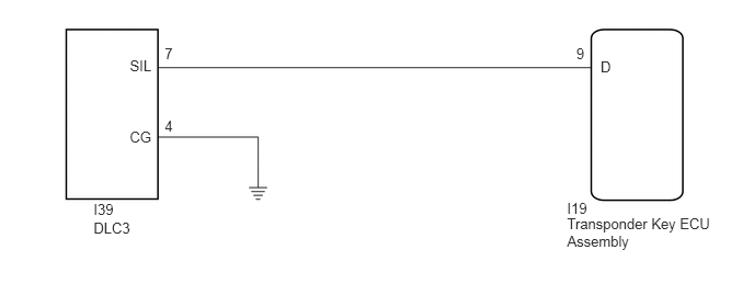
5.39,2.045 6.812,2.365
1.422,0.32
10
Transponder Key ECU Assembly
5.39,1.892 5.68,2.067
0.29,0.175
10
I19
5.708,0.55 5.855,0.725
0.147,0.175
10
D
5.477,0.432 5.624,0.607
0.147,0.175
10
9
1.565,0.432 1.711,0.607
0.147,0.175
10
7
1.565,1.113 1.711,1.288
0.147,0.175
10
4
0.889,2.085 1.273,2.226
0.384,0.141
10
DLC3
0.889,1.905 1.179,2.08
0.29,0.175
10
I39
1.234,0.544 1.487,0.719
0.253,0.175
10
SIL
1.234,1.214 1.487,1.389
0.253,0.175
10
CG
PROCEDURE
1.CHECK HARNESS AND CONNECTOR (DLC3 - TRANSPONDER KEY ECU AND BODY GROUND)
a.
Disconnect the DLC3 connector.
b.
Disconnect the transponder key ECU assembly connector.
c.
Measure the resistance according to the value(s) in the table below.
- Standard Resistance:
Tester Connection Condition Specified Condition I19-9 (D) - I39-7 (SIL) Always Below 1 Ω I39-4 (CG) - Body ground Always Below 1 Ω I19-9 (D) - Body ground Always 10 kΩ or higher I39-7 (SIL)- Body ground Always 10 kΩ or higher
- Result:
Proceed to OK NG
OK
PROCEED TO NEXT SUSPECTED AREA SHOWN IN PROBLEM SYMPTOMS TABLE
NG
REPAIR OR REPLACE HARNESS OR CONNECTOR