MIRROR (EXT) OUTER REAR VIEW MIRROR INSPECTION
PROCEDURE

 87908B
1.INSPECT MIRROR SUB-ASSEMBLY RH (w/ Memory)
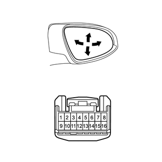
| *a | Component without harness connected
(Mirror Sub-assembly RH) |
Check the operation of the mirror surface.
Disconnect the mirror sub-assembly RH connector.
Apply battery voltage and check the operation of the mirror.
- OK:
Measurement Condition Specified Condition Battery positive (+) → Terminal 1 (RMVR)
Battery negative (-) → Terminal 10 (RM+R)Turns upward Battery positive (+) → Terminal 10 (RM+R)
Battery negative (-) → Terminal 1 (RMVR)Turns downward Battery positive (+) → Terminal 9 (RMHR)
Battery negative (-) → Terminal 10 (RM+R)Turns left Battery positive (+) → Terminal 10 (RM+R)
Battery negative (-) → Terminal 9 (RMHR)Turns right
If the result is not as specified, replace the mirror sub-assembly RH.
87909B
2.INSPECT MIRROR SUB-ASSEMBLY LH (w/ Memory)
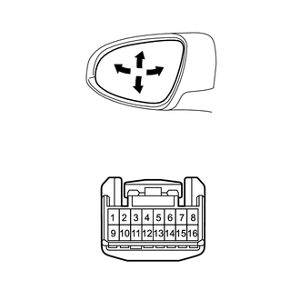
| *a | Component without harness connected
(Mirror Sub-assembly LH) |
Check the operation of the mirror surface.
Disconnect the mirror sub-assembly LH connector.
Apply battery voltage and check the operation of the mirror.
- OK:
Measurement Condition Specified Condition Battery positive (+) → Terminal 1 (LMVR)
Battery negative (-) → Terminal 10 (LM+R)Turns upward Battery positive (+) → Terminal 10 (LM+R)
Battery negative (-) → Terminal 1 (LMVR)Turns downward Battery positive (+) → Terminal 9 (LMHR)
Battery negative (-) → Terminal 10 (LM+R)Turns left Battery positive (+) → Terminal 10 (LM+R)
Battery negative (-) → Terminal 9 (LMHR)Turns right
If the result is not as specified, replace the mirror sub-assembly LH.
87908B
3.INSPECT MIRROR SUB-ASSEMBLY RH (w/o Memory)
Check the operation of the mirror surface.
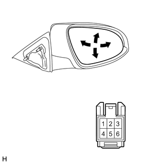
| *a | Component without harness connected
(Mirror Sub-assembly RH) |
Disconnect the mirror sub-assembly RH connector.
Apply battery voltage and check the operation of the mirror.
- OK:
Measurement Condition Specified Condition Battery positive (+) → Terminal 3 (MV)
Battery negative (-) → Terminal 4 (M+)Turns upward Battery positive (+) → Terminal 4 (M+)
Battery negative (-) → Terminal 3 (MV)Turns downward Battery positive (+) → Terminal 1 (MH)
Battery negative (-) → Terminal 4 (M+)Turns left Battery positive (+) → Terminal 4 (M+)
Battery negative (-) → Terminal 1 (MH)Turns right
If the result is not as specified, replace the mirror sub-assembly RH.
87909B
4.INSPECT MIRROR SUB-ASSEMBLY LH (w/o Memory)
Check the operation of the mirror surface.
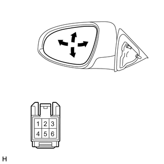
| *a | Component without harness connected
(Mirror Sub-assembly LH) |
Disconnect the mirror sub-assembly LH connector.
Apply battery voltage and check the operation of the mirror.
- OK:
Measurement Condition Specified Condition Battery positive (+) → Terminal 3 (MV)
Battery negative (-) → Terminal 4 (M+)Turns upward Battery positive (+) → Terminal 4 (M+)
Battery negative (-) → Terminal 3 (MV)Turns downward Battery positive (+) → Terminal 1 (MH)
Battery negative (-) → Terminal 4 (M+)Turns left Battery positive (+) → Terminal 4 (M+)
Battery negative (-) → Terminal 1 (MH)Turns right
If the result is not as specified, replace the mirror sub-assembly LH.