RM2030EQ
_59
Vehicle Exterior
_014680
LIGHTING (EXT)
_0074733
AUTOMATIC LIGHT CONTROL SENSOR
G
LIGHTING (EXT) AUTOMATIC LIGHT CONTROL SENSOR INSPECTION
PROCEDURE

 89120A
1.INSPECT AUTOMATIC LIGHT CONTROL SENSOR
a.
0.083,0.06 0.305,0.253
0.222,0.193
10
*a
0.807,1.294 1.199,1.544
0.392,0.25
0.895,1.337 1.12,1.487
0.226,0.149
10
I61
2.286,1.592 2.659,1.741
0.373,0.149
10
CLTB
0.691,1.82 1.069,1.969
0.378,0.149
10
CLTE
1.91,1.675 2.261,1.675
false
1.56,1.503 1.107,1.821
false
| *a | Front view of wire harness connector
(to Automatic Light Control Sensor) |
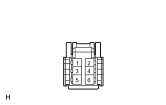
Disconnect the I61 automatic light control sensor connector.
b.
Measure the voltage and resistance according to the value(s) in the table below.
- Standard Voltage:
Tester Connection Condition Specified Condition I61-6 (CLTB) - I61-3 (CLTE) Ignition switch off Below 1 V Ignition switch ON 11 to 14 V
- Standard Resistance:
Tester Connection Condition Specified Condition I61-3 (CLTE) - Body ground Always Below 1 Ω
If the result is not as specified, there may be a malfunction on the wire harness side.
c.
0.155,0.11 0.357,0.266
0.203,0.156
10
*a
2.383,2.725 2.773,2.87
0.39,0.145
10
CLTS
2.535,2.376 2.921,2.52
0.385,0.145
10
CLTE
1.871,2.406 2.297,2.739
false
1.865,2.25 2.481,2.447
false
0.344,1.595 0.745,1.858
0.401,0.263
0.436,1.637 0.646,1.799
0.211,0.162
10
I61
| *a | Component with harness connected
(Automatic Light Control Sensor) |
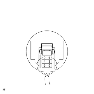
Reconnect the I61 automatic light control sensor connector.
d.
Connect an oscilloscope to the automatic light control sensor connector.
e.
2.953,1.027 3.297,1.187
0.344,0.16
10
GND
1.854,1.152 1.984,1.313
0.13,0.16
10
A
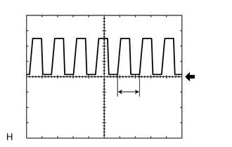
Check the waveform.
- OK:
Tester Connection Tool Setting Condition Specified Condition I61-3 (CLTE) - I61-5 (CLTS) 5 V/DIV., 5 ms./DIV Ignition switch ON, light control switch in AUTO position Correct waveform is as shown
- HINT:
-
If the ambient light becomes brighter, width A becomes narrower.
If the result is not as specified, the automatic light control sensor may have a malfunction.