Home › Drivetrain › U660E AUTOMATIC TRANSMISSION / TRANSAXLE › AUTOMATIC TRANSAXLE SYSTEM
RM2030EQ _52 Drivetrain _014643 U660E AUTOMATIC TRANSMISSION / TRANSAXLE _0076674 AUTOMATIC TRANSAXLE SYSTEM J

U660E AUTOMATIC TRANSMISSION / TRANSAXLE  AUTOMATIC TRANSAXLE SYSTEM  Shift Paddle Switch Circuit  


DESCRIPTION

Moving the shift lever to S enables gear selection. The driver can select the gear optionally by shifting the paddle to "+" or "-".

WIRING DIAGRAM
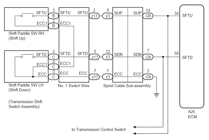
C239279E20
6.448,3.938 6.917,4.219 0.469,0.281 10 false ECM 6.25,1.896 6.677,2.063 0.427,0.167 10 false SFTD 6.25,0.448 6.781,0.75 0.531,0.302 10 false SFTU 1.24,1.792 1.667,1.958 0.427,0.167 10 false SFTD 1.24,0.354 1.667,0.521 0.427,0.167 10 false SFTU 1.313,2.469 1.656,2.625 0.344,0.156 10 false ECC 3.542,2.865 5.396,3.156 1.854,0.292 10 false Spiral Cable Sub-assembly 0.292,1.063 1.563,1.469 1.271,0.406 10 false Shift Paddle SW RH (Shift Up) 0.292,2.844 1.542,3.208 1.25,0.365 10 false Shift Paddle SW LH (Shift Down) 0.292,3.417 1.49,3.833 1.198,0.417 10 false (Transmission Shift Switch Assembly) 1.99,2.865 3.146,3.021 1.156,0.156 10 false No. 1 Switch Wire 2.458,4.375 4.469,4.552 2.01,0.177 10 false to Transmission Control Switch 3.917,1.792 4.229,1.938 0.313,0.146 10 false SDN 3.917,0.365 4.354,0.625 0.438,0.26 10 false SUP 4.573,0.365 5,0.583 0.427,0.219 10 false SUP 4.573,1.792 4.885,1.938 0.313,0.146 10 false SDN 3.917,2.469 4.26,2.625 0.344,0.156 10 false ECC 4.573,2.469 4.917,2.625 0.344,0.156 10 false ECC 2.063,2.438 2.406,2.594 0.344,0.156 10 false ECC 2.708,2.438 3.052,2.594 0.344,0.156 10 false ECC 2.063,2.104 2.458,2.26 0.396,0.156 10 false ECC1 2.063,0.719 2.458,0.875 0.396,0.156 10 false ECC1 2.063,1.76 2.49,1.927 0.427,0.167 10 false SFTD 2.063,0.354 2.49,0.521 0.427,0.167 10 false SFTU 2.656,1.76 3.083,1.927 0.427,0.167 10 false SFTD 2.656,0.354 3.083,0.521 0.427,0.167 10 false SFTU 6.448,3.76 6.917,4.01 0.469,0.25 10 false A25 5.979,0.375 6.281,0.688 0.302,0.313 10 false 34 5.979,1.75 6.24,1.99 0.26,0.24 10 false 50 4.99,0.458 5.365,0.75 0.375,0.292 10 false I28 3.625,0.458 3.979,0.719 0.354,0.26 10 false z3 3.146,2.563 3.396,2.802 0.25,0.24 10 false z17 5,0.271 5.365,0.49 0.365,0.219 10 false 14 5.042,1.656 5.229,1.802 0.188,0.146 10 false 7 5.042,2.354 5.229,2.5 0.188,0.146 10 false 2 3.667,0.26 3.854,0.406 0.188,0.146 10 false 6 3.656,2.354 3.844,2.5 0.188,0.146 10 false 7 3.625,1.688 3.906,1.958 0.281,0.271 10 false 12 3.219,2.354 3.406,2.5 0.188,0.146 10 false 7 3.208,1.688 3.417,1.927 0.208,0.24 10 false 3 3.188,0.271 3.375,0.417 0.188,0.146 10 false 2 1.802,0.271 1.99,0.417 0.188,0.146 10 false 3 1.802,0.635 1.99,0.781 0.188,0.146 10 false 2 1.802,2.385 1.99,2.531 0.188,0.146 10 false 3 1.802,1.688 1.99,1.833 0.188,0.146 10 false 2 1.802,2.042 1.99,2.188 0.188,0.146 10 false 4 1.26,2.135 1.656,2.292 0.396,0.156 10 false ECC1 1.26,0.719 1.875,1 0.615,0.281 10 false ECC1 4.99,1.885 5.396,2.125 0.406,0.24 10 false I28 4.99,2.563 5.448,2.813 0.458,0.25 10 false I28 3.625,1.875 3.865,2.094 0.24,0.219 10 false z3 3.625,2.563 3.875,2.781 0.25,0.219 10 false z3 3.146,1.885 3.417,2.167 0.271,0.281 10 false z17 3.125,0.469 3.385,0.698 0.26,0.229 10 false z17 1.792,0.458 2.063,0.729 0.271,0.271 10 false B 1.792,0.802 1.927,0.958 0.135,0.156 10 false B 1.792,1.885 2.01,2.094 0.219,0.208 10 false C 1.792,2.219 1.927,2.375 0.135,0.156 10 false C 1.792,2.563 1.927,2.719 0.135,0.156 10 false C

PROCEDURE

1.READ VALUE USING INTELLIGENT TESTER (SPORT SHIFT SWITCH STATUS)
a.

Connect the intelligent tester to the DLC3.


b.

Turn the ignition switch to ON.


c.

Turn the intelligent tester on.


d.

Enter the following menus: Powertrain / Engine / Data List.


e.

In accordance with the display on the intelligent tester, read the Data List.


Powertrain > Engine > Data List
Tester Display Measurement Item Range Normal Condition Diagnostic Note
Sports Shift Up SW Sport shift up switch status ON or OFF
·

ON: Continuously pull to "+" (up-shift)

·

OFF: Release "+" (up-shift)


-
Sports Shift Down SW Sport shift down switch status ON or OFF
·

ON: Continuously pull to "-" (down-shift)

·

OFF: Release "-" (down-shift)


-
Powertrain > Engine > Data List
Tester Display
Sports Shift Up SW
Sports Shift Down SW
50003 234 134,135
Result:
Result Proceed to
Data display is not within Normal Condition range A
Data display is within Normal Condition range B


A

2.CHECK HARNESS AND CONNECTOR (SHIFT PADDLE SWITCH CIRCUIT)

B

2.CHECK HARNESS AND CONNECTOR (SHIFT PADDLE SWITCH CIRCUIT)
a.
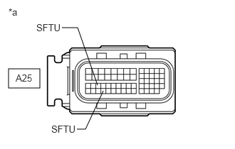
C233487C07
0.125,1.01 0.583,1.292 0.458,0.281 1.427,1.25 1.135,0.406 1.135,0.406 0.906,0.406 false 1.51,1.333 1.25,1.896 1.25,1.896 1.125,1.896 false 0.125,0.094 0.469,0.458 0.344,0.365 10 *a 0.229,1.063 0.677,1.354 0.448,0.292 10 A25 0.531,0.323 1.073,0.635 0.542,0.313 10 SFTU 0.75,1.813 1.271,2.021 0.521,0.208 10 SFTU
*a Front view of wire harness connector
(to ECM)


Disconnect the ECM connector.


b.

Measure the resistance according to the value(s) in the table below.

Standard Resistance:
Tester Connection Switch Condition Specified Condition
A25-50 (SFTD) - Body ground Pull "-" continuously
(Down-shift)
Below 1 Ω
Release 10 kΩ or higher
A25-34 (SFTU) - Body ground Pull "+" continuously
(Up-shift)
Below 1 Ω
Release 10 kΩ or higher


Result:
Proceed to
OK
NG


OK

NG

3.CHECK HARNESS AND CONNECTOR (SPIRAL CABLE - BODY GROUND)
a.

Disconnect the negative (-) terminal cable from the battery.


b.

Wait for at least 90 seconds.


c.

Remove the steering wheel assembly.


d.

Remove the steering column cover.


e.
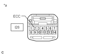
C136967C04
0.438,0.938 0.927,1.229 0.49,0.292 1.354,1.073 1,0.635 1,0.635 0.854,0.635 false 0.146,0.125 0.448,0.354 0.302,0.229 10 false *a 0.531,0.563 0.885,0.719 0.354,0.156 10 false ECC 0.594,1 0.854,1.177 0.26,0.177 10 false l28
*a Front view of wire harness connector
(to Spiral Cable Sub-assembly)


Disconnect the spiral cable connector.


f.

Measure the resistance according to the value(s) in the table below.

Standard Resistance:
Tester Connection Condition Specified Condition
l28-2 (ECC) - Body ground Always Below 1 Ω


Result:
Proceed to
OK
NG


OK

4.CHECK HARNESS AND CONNECTOR (SPIRAL CABLE - ECM)

NG

REPAIR OR REPLACE HARNESS OR CONNECTOR

4.CHECK HARNESS AND CONNECTOR (SPIRAL CABLE - ECM)
a.

Disconnect the ECM connector.


b.

Measure the resistance according to the value(s) in the table below.

Standard Resistance:
Tester Connection Condition Specified Condition
A25-50 (SFTD) - l28-7 (SDN) Always Below 1 Ω
A25-50 (SFTD) or l28-7 (SDN) - Body ground Always 10 kΩ or higher
A25-34 (SFTU) - l28-14 (SUP) Always Below 1 Ω
A25-34 (SFTU) or l28-14 (SUP) - Body ground Always 10 kΩ or higher


Result:
Proceed to
OK
NG


OK

5.CHECK HARNESS AND CONNECTOR (SPIRAL CABLE - SHIFT PADDLE SWITCH)

NG

REPAIR OR REPLACE HARNESS OR CONNECTOR

5.CHECK HARNESS AND CONNECTOR (SPIRAL CABLE - SHIFT PADDLE SWITCH)
a.
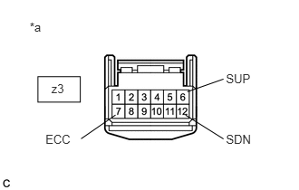
C245153C02
0.342,0.229 0.568,0.406 0.226,0.177 10 *a 2.598,0.826 2.932,0.979 0.333,0.153 10 SUP 2.598,1.522 2.932,1.675 0.333,0.153 10 SDN 0.523,1.522 0.856,1.675 0.333,0.153 10 ECC 2.153,1.056 2.569,0.91 false 2.133,1.325 2.569,1.599 false 1.328,1.323 0.932,1.597 false 0.436,0.883 0.923,1.175 0.487,0.292 0.591,0.939 0.762,1.121 0.171,0.182 10 z3
*a Front view of wire harness connector
(to Spiral Cable Sub-assembly)


Remove the horn button assembly.


b.

Disconnect the steering pad switch connector from the spiral cable sub-assembly.
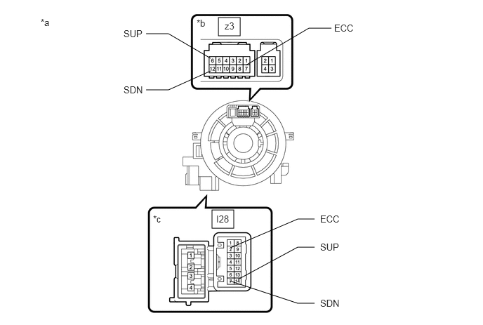

c.

Measure the resistance according to the value(s) in the table below when the shift paddle switch is moved to each position.

Standard Resistance:
Tester Connection Switch Condition Specified Condition
z3-6 (SUP) - z3-7 (ECC) Pull "+" continuously
(Up-shift)
Below 1 Ω
Release 10 kΩ or higher
z3-12 (SDN) - z3-7 (ECC) Pull "-" continuously
(Down-shift)
Below 1 Ω
Release 10 kΩ or higher


Result:
Proceed to
OK
NG


OK

6.INSPECT SPIRAL CABLE SUB-ASSEMBLY

NG

7.INSPECT TRANSMISSION SHIFT SWITCH ASSEMBLY (SHIFT PADDLE SWITCH)
6.INSPECT SPIRAL CABLE SUB-ASSEMBLY
a.

Disconnect the steering pad switch connector from the spiral cable sub-assembly.

C275094C01
3.24,0.26 3.563,0.531 0.323,0.271 3.146,3.115 3.469,3.385 0.323,0.271 3.646,0.969 4.583,0.417 4.583,0.417 4.917,0.417 false 3.125,0.865 2.5,0.5 2.5,0.5 2.167,0.5 false 3.125,1.052 2.5,1.333 2.5,1.333 2.167,1.333 false 3.417,3.677 4.417,3.25 4.417,3.25 4.667,3.25 false 3.531,4.146 4.417,3.667 4.417,3.667 4.667,3.667 false 3.406,4.167 4.417,4.5 4.417,4.5 4.667,4.5 false 0.604,0.25 0.917,0.406 0.313,0.156 10 *a 2.917,0.26 3.229,0.417 0.313,0.156 10 *b 2.271,3.167 2.583,3.323 0.313,0.156 10 *c 1.833,0.417 2.292,0.615 0.458,0.198 10 SUP 1.833,1.25 2.292,1.448 0.458,0.198 10 SDN 4.958,0.333 5.417,0.531 0.458,0.198 10 ECC 3.333,0.302 3.646,0.5 0.313,0.198 10 z3 3.208,3.167 3.667,3.365 0.458,0.198 10 I28 4.75,4.417 5.208,4.615 0.458,0.198 10 SDN 4.75,3.583 5.208,3.781 0.458,0.198 10 SUP 4.75,3.167 5.208,3.365 0.458,0.198 10 ECC
*a Component without harness connected
(Spiral Cable Sub-assembly)
*b Steering Pad Switch Side
*c Vehicle Side - -


b.

Measure the resistance according to the value(s) in the table below.

Standard Resistance:
Tester Connection Condition Specified Condition
z3-7 (ECC) - l28-2 (ECC) Always Below 3 Ω
z3-6 (SUP) - l28-14 (SUP) Always Below 3 Ω
z3-12 (SDN) - l28-7 (SDN) Always Below 3 Ω
z3-7 (ECC) or l28-2 (ECC) - All other terminals Always 10 kΩ or higher
z3-6 (SUP) or l28-14 (SUP) - All other terminals Always 10 kΩ or higher
z3-12 (SDN) or l28-7 (SDN) - All other terminals Always 10 kΩ or higher


Result:
Proceed to
OK
NG


OK

NG

7.INSPECT TRANSMISSION SHIFT SWITCH ASSEMBLY (SHIFT PADDLE SWITCH)
a.
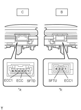
C207558C07
0.719,0.375 1.208,0.667 0.49,0.292 2.375,0.375 2.865,0.667 0.49,0.292 2.667,2.99 2.885,3.333 false 2.521,2.99 2.302,3.333 false 1.063,3.083 1.344,3.333 false 0.938,3.083 0.875,3.323 false 0.813,3.073 0.438,3.313 false 0.771,3.719 1.083,3.917 0.313,0.198 10 *a 2.5,3.719 2.813,3.917 0.313,0.198 10 *b 2.063,3.344 2.469,3.51 0.406,0.167 10 SFTU 1.146,3.354 1.552,3.521 0.406,0.167 10 SFTD 2.729,3.344 3.156,3.51 0.427,0.167 10 ECC1 0.177,3.333 0.604,3.5 0.427,0.167 10 ECC1 0.698,3.344 1.052,3.51 0.354,0.167 10 ECC 0.906,0.427 1.042,0.573 0.135,0.146 10 C 2.573,0.427 2.698,0.573 0.125,0.146 10 B
*a Component without harness connected
(Shift paddle switch LH)
*b Component without harness connected
(Shift paddle switch RH)


Disconnect the connector from the transmission shift switch LH and RH.


b.

Measure the resistance according to the value(s) in the table below.

Standard Resistance:
Transmission Shift Switch LH:
Tester Connection Switch Condition Specified Condition
C-3 (ECC) - C-2 (SFTD) Pull "-" continuously
(Down-shift)
Below 1 Ω
Release 10 kΩ or higher
C-4 (ECC1) - C-2 (SFTD) Pull "-" continuously
(Down-shift)
Below 1 Ω
Release 10 kΩ or higher

Transmission Shift Switch RH:
Tester Connection Switch Condition Specified Condition
B-3 (SFTU) - B-2 (ECC1) Pull "+" continuously
(Up-shift)
Below 1 Ω
Release 10 kΩ or higher


Result:
Proceed to
OK
NG


OK

8.INSPECT NO. 1 SWITCH WIRE

NG

REPLACE TRANSMISSION SHIFT SWITCH ASSEMBLY (SHIFT PADDLE SWITCH)

8.INSPECT NO. 1 SWITCH WIRE
a.

Connect the transmission shift switch LH and RH connector.

b.
C245155C07
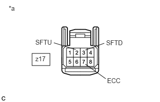
0.688,1.146 1.073,1.406 0.385,0.26 1.625,1.063 1.156,0.917 false 1.833,1.073 2.24,0.927 false 1.833,1.375 2.271,1.688 false 0.188,0.094 0.396,0.271 0.208,0.177 10 false *a 2.302,1.646 2.646,1.813 0.344,0.167 10 false ECC 2.281,0.833 2.698,1 0.417,0.167 10 false SFTD 0.76,0.823 1.177,0.99 0.417,0.167 10 false SFTU 0.76,1.177 1,1.375 0.24,0.198 10 false z17
*a Front view of wire harness connector
(to Steering Pad Switch Connector)


Disconnect the No.1 switch wire from steering pad switch connector.


c.

Measure the resistance according to the value(s) in the table below.

Standard Resistance:
Tester Connection Switch Condition Specified Condition
z17-3 (SFTD) - z17-7 (ECC) Pull "-" continuously
(Down-shift)
Below 1 Ω
Release 10 kΩ or higher
z17-2 (SFTU) - z17-7 (ECC) Pull "+" continuously
(Down-shift)
Below 1 Ω
Release 10 kΩ or higher


Result:
Proceed to
OK
NG


OK

REPAIR OR REPLACE HARNESS OR CONNECTOR (NO. 1 SWITCH WIRE - SPIRAL CABLE SUB-ASSEMBLY)

NG