Home › Vehicle Interior › LIGHTING (INT) › LIGHTING SYSTEM › 2012.02–2015.04
RM2030EQ _58 Vehicle Interior _014666 LIGHTING (INT) _0074614 LIGHTING SYSTEM J

LIGHTING (INT)  LIGHTING SYSTEM  Interior Light Auto Cut Circuit  


DESCRIPTION

The main body ECU (multiplex network body ECU) controls operation of the light cut relay in order to supply power to the interior lights. When battery saving control operates while the interior lights are on, the main body ECU (multiplex network body ECU) opens the light cut relay to turn off the lights.

WIRING DIAGRAM
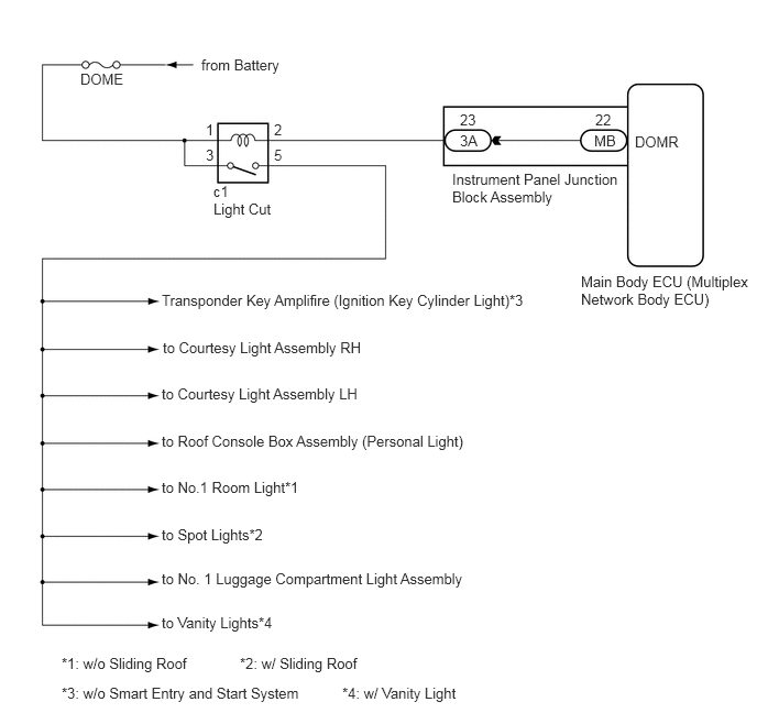
E230654E05
2.271,6.198 3.531,6.375 1.26,0.177 10 false *2: w/ Sliding Roof 1.906,0.531 2.844,0.906 0.938,0.375 10 false from Battery 6.01,1.26 6.635,1.552 0.625,0.292 10 false DOMR 0.76,0.667 1.198,0.969 0.438,0.302 10 false DOME 2.021,1.729 2.333,1.906 0.313,0.177 10 false c1 2.021,1.896 2.813,2.177 0.792,0.281 10 false Light Cut 5.635,1.052 6.042,1.385 0.406,0.333 10 false 22 5.625,1.25 6.021,1.49 0.396,0.24 10 false MB 4.354,1.052 4.615,1.385 0.26,0.333 10 false 23 2.594,1.146 2.948,1.5 0.354,0.354 10 false 2 2.594,1.385 2.854,1.677 0.26,0.292 10 false 5 1.948,1.146 2.26,1.417 0.313,0.271 10 false 1 1.948,1.385 2.188,1.688 0.24,0.302 10 false 3 4.354,1.25 4.771,1.542 0.417,0.292 10 false 3A 4.281,1.615 5.896,2.021 1.615,0.406 10 false Instrument Panel Junction Block Assembly 5.5,2.583 7.115,3.063 1.615,0.479 10 false Main Body ECU (Multiplex Network Body ECU) 0.583,6.198 1.844,6.375 1.26,0.177 10 false *1: w/o Sliding Roof 1.531,4.531 2.875,4.708 1.344,0.177 10 false to No.1 Room Light*1 1.531,4.979 2.594,5.156 1.063,0.177 10 false to Spot Lights*2 1.531,4.094 4.552,4.271 3.021,0.177 10 false to Roof Console Box Assembly (Personal Light) 1.531,3.646 3.51,3.823 1.979,0.177 10 false to Courtesy Light Assembly LH 1.542,3.208 3.729,3.406 2.188,0.198 10 false to Courtesy Light Assembly RH 1.531,5.813 2.656,5.99 1.125,0.177 10 false to Vanity Lights*4 1.531,5.396 4.49,5.573 2.958,0.177 10 false to No. 1 Luggage Compartment Light Assembly 1.531,2.76 5.135,3.01 3.604,0.25 10 false Transponder Key Amplifire (Ignition Key Cylinder Light)*3 0.583,6.479 3.01,6.667 2.427,0.188 10 false *3: w/o Smart Entry and Start System 3.24,6.479 4.406,6.656 1.167,0.177 10 false *4: w/ Vanity Light

CAUTION / NOTICE / HINT

NOTICE:

Inspect the fuses for circuits related to this system before performing the following procedure.


PROCEDURE

1.CHECK SYMPTOMS
a.

Check symptoms.

Result:
Result Proceed to
All the interior lights that receive power via the light cut relay do not illuminate. A
Battery saving function does not operate. B


A

2.INSPECT LIGHT CUT RELAY

B

7.PERFORM ACTIVE TEST USING INTELLIGENT TESTER
2.INSPECT LIGHT CUT RELAY
a.

Remove the light cut relay from the c1 light cut relay connector.
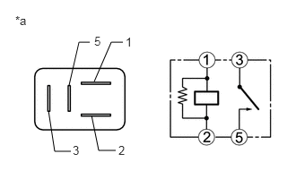

b.
E222294C10
1.094,0.948 1.292,0.49 1.292,0.49 1.427,0.49 false 1.063,1.344 1.146,1.75 1.146,1.75 1.344,1.75 false 0.802,0.99 0.917,0.49 0.917,0.49 1.042,0.49 false 0.563,1.292 0.635,1.76 0.635,1.76 0.823,1.76 false 1.458,0.406 1.563,0.563 0.104,0.156 10 1 1.375,1.667 1.479,1.823 0.104,0.156 10 2 1.094,0.396 1.198,0.552 0.104,0.156 10 5 0.177,0.156 0.333,0.313 0.156,0.156 10 *a 0.844,1.667 0.948,1.823 0.104,0.156 10 3
*a Component without harness connected
(Light Cut Relay)


Measure the resistance according to the value(s) in the table below.

Standard Resistance:
Tester Connection Condition Specified Condition
3 - 5 Voltage is not applied between terminals 1 and 2 10 kΩ or higher
3 - 5 Voltage is applied between terminals 1 and 2 Below 1 Ω


Result:
Proceed to
OK
NG


OK

3.CHECK HARNESS AND CONNECTOR (DOME FUSE - LIGHT CUT RELAY)

NG

REPLACE LIGHT CUT RELAY

3.CHECK HARNESS AND CONNECTOR (DOME FUSE - LIGHT CUT RELAY)
a.

Measure the voltage according to the value(s) in the table below.

Standard Voltage:
Tester Connection Switch Condition Specified Condition
c1-1 - Body ground Ignition switch off 11 to 14 V
c1-3 - Body ground Ignition switch off 11 to 14 V


Result:
Proceed to
OK
NG


OK

4.CHECK HARNESS AND CONNECTOR (LIGHT CUT RELAY)

NG

REPAIR OR REPLACE HARNESS OR CONNECTOR

4.CHECK HARNESS AND CONNECTOR (LIGHT CUT RELAY)
a.

Install the light cut relay to the c1 light cut relay connector.
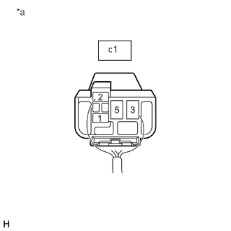

b.
E227040C02
0.243,0.099 0.659,0.422 0.416,0.323 10 *a 1.463,0.606 1.95,0.899 0.487,0.292 1.611,0.651 1.834,0.869 0.223,0.218 10 c1
*a Component with harness connected
(Light Cut Relay)


Measure the voltage according to the value(s) in the table below.
Standard Voltage:
Tester Connection Switch Condition Specified Condition
c1-5 - Body ground Ignition switch ON 11 to 14 V


Result:
Proceed to
OK
NG


OK

REPAIR OR REPLACE HARNESS OR CONNECTOR (LIGHT CUT RELAY - EACH LIGHT)

NG

5.CHECK HARNESS AND CONNECTOR (LIGHT CUT RELAY - INSTRUMENT PANEL JUNCTION BLOCK ASSEMBLY)
a.

Remove the light cut relay from the c1 light cut relay connector.


b.

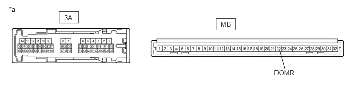
Disconnect the 3A instrument panel junction block assembly connector.


c.

Measure the resistance according to the value(s) in the table below.

Standard Resistance:
Tester Connection Condition Specified Condition
c1-2 - 3A-23 Always Below 1 Ω
c1-2 - Body ground Always 10 kΩ or higher


Result:
Proceed to
OK
NG


OK

6.INSPECT INSTRUMENT PANEL JUNCTION BLOCK ASSEMBLY

NG

REPAIR OR REPLACE HARNESS OR CONNECTOR

6.INSPECT INSTRUMENT PANEL JUNCTION BLOCK ASSEMBLY
a.

Remove the instrument panel junction block assembly.

Click herePower Source / Network>POWER DISTRIBUTION>MAIN BODY ECU>REMOVAL


b.

Remove the main body ECU (multiplex network body ECU) from the instrument panel junction block assembly.


c.

Measure the resistance according to the value(s) in the table below.

E227400C02
0.184,0.105 0.48,0.326 0.295,0.221 10 *a 1.206,0.237 1.603,0.476 0.397,0.238 4.414,0.382 4.811,0.62 0.397,0.238 4.508,0.42 5.143,0.625 0.635,0.205 10 MB 1.313,0.28 1.949,0.485 0.635,0.205 10 3A 5.596,1.422 6.093,1.573 0.497,0.151 10 DOMR 5.705,1.029 5.817,1.422 false
*a Component without harness connected
(Instrument Panel Junction Block Assembly)
- -


Standard Resistance:
Tester Connection Switch Condition Specified Condition
3A-23 - MB-22 (DOMR) Always Below 1 Ω


Result:
Proceed to
OK
NG


OK

PROCEED TO NEXT SUSPECTED AREA SHOWN IN PROBLEM SYMPTOMS TABLE

NG

REPLACE INSTRUMENT PANEL JUNCTION BLOCK ASSEMBLY

7.PERFORM ACTIVE TEST USING INTELLIGENT TESTER
a.

Connect the intelligent tester to the DLC3.


b.

Turn the ignition switch to ON.


c.

Turn the intelligent tester on.


d.

Enter the following menus: Body / Main Body / Active Test.


e.

Check that the relay operates.

Body Electrical > Main Body > Active Test
Tester Display Measurement Item Control Range Diagnostic Note
Relay for Interior Light Auto Cut Function Light Cut Relay ON/OFF -
Body Electrical > Main Body > Active Test
Tester Display
Relay for Interior Light Auto Cut Function
50004 123 66
OK:

Light auto cut relay operates.


Result:
Proceed to
OK
NG


OK

PROCEED TO NEXT SUSPECTED AREA SHOWN IN PROBLEM SYMPTOMS TABLE

NG

8.INSPECT LIGHT CUT RELAY
a.

Remove the light cut relay from the c1 light cut relay connector.


b.
E222294C10
1.094,0.948 1.292,0.49 1.292,0.49 1.427,0.49 false 1.063,1.344 1.146,1.75 1.146,1.75 1.344,1.75 false 0.802,0.99 0.917,0.49 0.917,0.49 1.042,0.49 false 0.563,1.292 0.635,1.76 0.635,1.76 0.823,1.76 false 1.458,0.406 1.563,0.563 0.104,0.156 10 1 1.375,1.667 1.479,1.823 0.104,0.156 10 2 1.094,0.396 1.198,0.552 0.104,0.156 10 5 0.177,0.156 0.333,0.313 0.156,0.156 10 *a 0.844,1.667 0.948,1.823 0.104,0.156 10 3
*a Component without harness connected
(Light Cut Relay)


Measure the resistance according to the value(s) in the table below.

Standard Resistance:
Tester Connection Condition Specified Condition
3 - 5 Voltage is not applied between terminals 1 and 2 10 kΩ or higher
3 - 5 Voltage is applied between terminals 1 and 2 Below 1 Ω


Result:
Proceed to
OK
NG


OK

9.CHECK HARNESS AND CONNECTOR (LIGHT CUT RELAY - INSTRUMENT PANEL JUNCTION BLOCK ASSEMBLY)

NG

REPLACE LIGHT CUT RELAY

9.CHECK HARNESS AND CONNECTOR (LIGHT CUT RELAY - INSTRUMENT PANEL JUNCTION BLOCK ASSEMBLY)
a.

Disconnect the 3A instrument panel junction block assembly connector.


b.

Measure the resistance according to the value(s) in the table below.

Standard Resistance:
Tester Connection Condition Specified Condition
c1-2 - 3A-23 Always Below 1 Ω
c1-2 - Body ground Always 10 kΩ or higher


Result:
Proceed to
OK
NG


OK

10.INSPECT INSTRUMENT PANEL JUNCTION BLOCK ASSEMBLY

NG

REPAIR OR REPLACE HARNESS OR CONNECTOR

10.INSPECT INSTRUMENT PANEL JUNCTION BLOCK ASSEMBLY
a.

Remove the instrument panel junction block assembly.

Click herePower Source / Network>POWER DISTRIBUTION>MAIN BODY ECU>REMOVAL


b.

Remove the main body ECU (multiplex network body ECU) from the instrument panel junction block assembly.


c.

Measure the resistance according to the value(s) in the table below.

E227400C02
0.184,0.105 0.48,0.326 0.295,0.221 10 *a 1.206,0.237 1.603,0.476 0.397,0.238 4.414,0.382 4.811,0.62 0.397,0.238 4.508,0.42 5.143,0.625 0.635,0.205 10 MB 1.313,0.28 1.949,0.485 0.635,0.205 10 3A 5.596,1.422 6.093,1.573 0.497,0.151 10 DOMR 5.705,1.029 5.817,1.422 false
*a Component without harness connected
(Instrument Panel Junction Block Assembly)
- -


Standard Resistance:
Tester Connection Condition Specified Condition
3A-23 - MB-22 (DOMR) Always Below 1 Ω
3A-23 - Body ground Always 10 kΩ or higher


Result:
Proceed to
OK
NG


OK

REPLACE MAIN BODY ECU (MULTIPLEX NETWORK BODY ECU)

NG

REPLACE INSTRUMENT PANEL JUNCTION BLOCK ASSEMBLY