RM2030EQ
_59
Vehicle Exterior
_014680
LIGHTING (EXT)
_0074739
AFS (ADAPTIVE FRONT-LIGHTING SYSTEM)
J
LIGHTING (EXT) AFS (ADAPTIVE FRONT-LIGHTING SYSTEM) AFS ECU Power Source Circuit
DESCRIPTION
This circuit detects the state of the ignition switch, and sends it to the AFS ECU (headlight swivel ECU assembly).
WIRING DIAGRAM
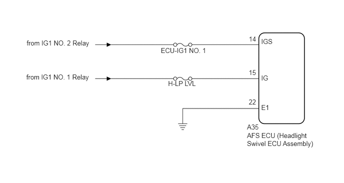
0.555,0.815 1.917,1.017
1.363,0.202
10
from IG1 NO. 2 Relay
0.549,1.52 1.911,1.721
1.363,0.202
10
from IG1 NO. 1 Relay
3.351,0.966 4.369,1.139
1.018,0.173
10
ECU-IG1 NO. 1
3.502,1.658 4.136,1.817
0.634,0.159
10
H-LP LVL
5.146,2.736 6.601,3.081
1.454,0.345
10
AFS ECU (Headlight Swivel ECU Assembly)
5.442,0.785 5.75,0.94
0.308,0.155
10
IGS
5.442,1.541 5.651,1.696
0.209,0.155
10
IG
5.442,2.152 5.651,2.307
0.209,0.155
10
E1
5.146,2.565 5.455,2.736
0.308,0.17
10
A35
5.182,2.046 5.395,2.232
0.212,0.186
10
22
5.182,1.427 5.395,1.613
0.212,0.186
10
15
5.184,0.732 5.397,0.918
0.212,0.186
10
14
PROCEDURE
1.CHECK HARNESS AND CONNECTOR (BATTERY - AFS ECU (HEADLIGHT SWIVEL ECU ASSEMBLY))
a.
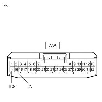
1.531,1.417 2.01,1.656
0.479,0.24
0.396,2.396 0.396,2.802
false
0.552,2.385 0.938,2.802
false
0.135,0.115 0.323,0.292
0.188,0.177
10
*a
1.656,1.458 2.25,1.813
0.594,0.354
10
A35
0.292,2.833 0.781,3.167
0.49,0.333
10
IGS
0.927,2.844 1.406,3.115
0.479,0.271
10
IG
| *a | Front view of wire harness connector
(to AFS ECU (Headlight Swivel ECU Assembly)) |
Disconnect the A35 AFS ECU (headlight swivel ECU assembly) connector.
b.
Measure the voltage according to the value(s) in the table below.
- Standard Voltage:
Tester Connection Condition Specified Condition A35-14 (IGS) - Body ground Ignition switch ON 11 to 14 V Ignition switch off Below 1 V A35-15 (IG) - Body ground Ignition switch ON 11 to 14 V Ignition switch off Below 1 V
- Result:
Proceed to OK NG
OK
2.CHECK HARNESS AND CONNECTOR (AFS ECU (HEADLIGHT SWIVEL ECU ASSEMBLY) - BODY GROUND)
NG
REPAIR OR REPLACE HARNESS OR CONNECTOR
2.CHECK HARNESS AND CONNECTOR (AFS ECU (HEADLIGHT SWIVEL ECU ASSEMBLY) - BODY GROUND)
a.
Measure the resistance according to the value(s) in the table below.
- Standard Resistance:
Tester Connection Condition Specified Condition A35-22 (E1) - Body ground Always Below 1 Ω
- Result:
Proceed to OK NG
OK
PROCEED TO NEXT SUSPECTED AREA SHOWN IN PROBLEM SYMPTOMS TABLE
Click hereVehicle Exterior>LIGHTING (EXT)>AFS (ADAPTIVE FRONT-LIGHTING SYSTEM)>PROBLEM SYMPTOMS TABLE
NG
REPAIR OR REPLACE HARNESS OR CONNECTOR