RM2030EQ
_51
Engine / Hybrid System
_014642
CRUISE CONTROL
_0165902
LANE DEPARTURE ALERT SYSTEM
U
CRUISE CONTROL LANE DEPARTURE ALERT SYSTEM TERMINALS OF ECU
CHECK LANE DEPARTURE WARNING CAMERA

1.896,0.781 2.271,1.031
0.375,0.25
1.969,0.823 2.281,1.021
0.313,0.198
10
false
S15
| Terminal No. (Symbol) | Wiring Color | Terminal Description | Condition | Specified Condition |
|---|---|---|---|---|
| S15-4 (LKSW) - S15-11 (GND) | R - BR | Lane-keeping assist main switch signal | Engine switch on (IG), lane-keeping assist main switch off | 4 V or higher |
| S15-4 (LKSW) - S15-11 (GND) | R - BR | Lane-keeping assist main switch signal | Engine switch on (IG), lane-keeping assist main switch on | Below 1 V |
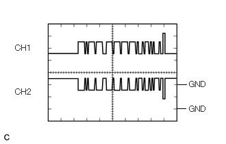
| S15-6 (CA1P) - S15-11 (GND) | V - BR | CAN communication signal | Engine switch on (IG) | Pulse generation
(Waveform 1) |
| S15-7 (IGB) - S15-11 (GND) | GR - BR | Power source | Engine switch on (IG) | 11 to 14 V |
| S15-11 (GND) - Body ground | BR - Body ground | Ground | Always | Below 1 Ω |
| S15-12 (CA1N) - S15-11 (GND) | LG - BR | CAN communication signal | Engine switch on (IG) | Pulse generation (Waveform 1) |
If the result is not as specified, there may be a malfunction on the wire harness side.
- HINT:
-
Oscilloscope waveform samples are provided here for reference only. Noise and fluctuating waveforms have been omitted.
a.
2.833,1.281 2.698,1.281
false
2.823,1.646 2.688,1.646
false
2.875,1.208 3.229,1.365
0.354,0.156
10
false
GND
2.875,1.583 3.229,1.74
0.354,0.156
10
false
GND
0.229,0.656 0.552,0.823
0.323,0.167
10
false
CH1
0.229,1.323 0.552,1.49
0.323,0.167
10
false
CH2
Waveform 1 (CAN communication signal)
| Item | Content |
|---|---|
| Terminal Name | CH1: S15-6 (CA1P) - S15-11 (GND)
CH2: S15-12 (CA1N) - S15-11 (GND) |
| Tester Range | 1 V/DIV., 50 μs./DIV. |
| Condition | Engine switch on (IG) |
- HINT:
-
The waveform will vary depending on the content of the digital communication (digital signal).