Home › Engine / Hybrid System › 2AR-FXE ENGINE CONTROL › SFI SYSTEM
NM2040EQ _51 Engine / Hybrid System _014482 2AR-FXE ENGINE CONTROL _0073579 SFI SYSTEM DE DETAILS F

2AR-FXE ENGINE CONTROL  SFI SYSTEM  DETAILS  VVT-i CONTROL  


OPERATION


a.

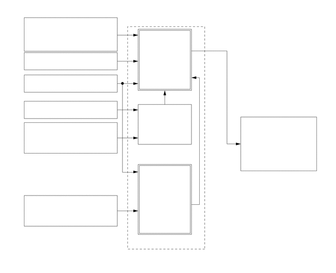
Based on engine speed, intake air volume, throttle position and engine coolant temperature, the ECM calculates optimal valve timing for all driving conditions. The ECM also controls the camshaft timing oil control valve assembly. In addition, the ECM uses signals from the camshaft position sensor and the crank position sensor to detect the actual valve timing, thus providing feedback control to achieve the target valve timing.
W105581
0.625,0.385 2.333,0.792 1.708,0.406 10 false Intake Mass Air Flow Meter Sub-assembly 0.729,1.115 3.052,1.438 2.323,0.323 10 false Throttle Position Sensor 0.781,1.594 2.24,1.917 1.458,0.323 10 false Crank Position Sensor 0.823,2.625 2.292,3.01 1.469,0.385 10 false E. F. I. Engine Coolant Temperature Sensor 0.688,4.167 2.573,4.49 1.885,0.323 10 false Camshaft Position Sensor 3.302,5.365 4.104,5.542 0.802,0.177 10 false ECM 3.125,0.781 3.938,1.229 0.813,0.448 10 false Target Valve Timing 3.229,2.365 3.99,2.688 0.76,0.323 10 false Correction 3.146,3.656 3.969,4.094 0.823,0.438 10 false Actual Valve Timing 3.573,3.177 4.24,3.333 0.667,0.156 10 false Feedback 4.906,1.302 6.219,1.583 1.313,0.281 10 false Duty-cycle Control 5.188,2.51 6.667,3.01 1.479,0.5 10 false Camshaft Timing Oil Control Valve Assembly 0.792,2.167 2.26,2.49 1.469,0.323 10 false Vehicle Speed Signal


b.

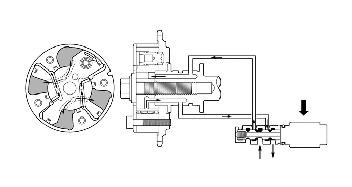
When the camshaft timing oil control valve assembly is positioned as illustrated below by the advance signals from the ECM, the resultant oil pressure is applied to the timing advance side vane chamber to rotate the camshaft in the timing advance direction.
W105582
5.281,3.167 4.813,3.167 true 1.083,2.469 1.083,2.969 true 1.771,1.083 1.771,0.458 1.771,0.458 1.698,0.458 false 6.094,1.823 6.24,1.969 0.146,0.146 10 false *2 1.521,0.344 1.719,0.521 0.198,0.177 10 false *a 1.01,3 1.365,3.188 0.354,0.188 10 false *1 4.625,3.063 4.823,3.229 0.198,0.167 10 false *b 5.219,3.25 5.396,3.417 0.177,0.167 10 false *c 5.51,3.271 5.875,3.438 0.365,0.167 10 false *d
*1 Vane *2 ECM
*a Rotation Direction *b Oil Pressure
*c In *d Drain


c.

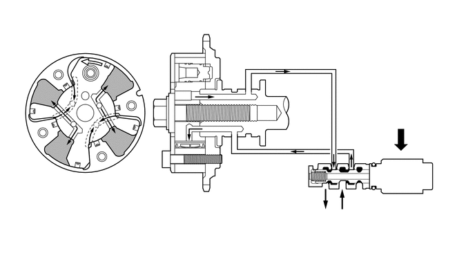
When the camshaft timing oil control valve assembly is positioned as illustrated below by the retard signals from the ECM, the resultant oil pressure is applied to the timing retard side vane chamber to rotate the camshaft in the timing retard direction.
W105584
5.615,3.052 5.156,3.052 true 1.094,2.417 1.094,2.917 true 1.365,0.906 1.365,0.573 1.365,0.573 1.5,0.573 true 6,1.719 6.188,1.865 0.188,0.146 10 false *2 1.563,0.458 2.708,0.625 1.146,0.167 9 false *a 1.031,2.958 1.385,3.146 0.354,0.188 10 false *1 5.656,2.958 6.458,3.125 0.802,0.167 10 false *b 5.125,3.177 5.302,3.344 0.177,0.167 10 false *c 4.833,3.177 5.01,3.344 0.177,0.167 10 false *d
*1 Vane *2 ECM
*a Rotation Direction *b Oil Pressure
*c In *d Drain


d.

After reaching the target timing, the engine valve timing is maintained by keeping the camshaft timing oil control valve assembly in the neutral position unless the engine operating conditions change. This maintains the engine valve timing at the desired target position by preventing the engine oil from running out of the camshaft timing oil control valve assembly.