HYBRID / BATTERY CONTROL HYBRID BATTERY SYSTEM GENERAL GENERAL
SPECIFICATION
HV Battery
| Item | Specification | |
|---|---|---|
| Type | Nickel Metal Hydride (Ni-MH) Battery | |
| Cell Quantity | 204 Cells (6 Cells x 34 Modules) | |
| Nominal Voltage | V | 244.8 |
| Battery Capacity (3HR) | Ah | 6.5 |
Cooling System (for HV Battery)
| Item | Specification | ||
|---|---|---|---|
| Battery Cooling Blower Assembly | Motor Type | Brushless | |
| Fan Type | Sirocco Fan | ||
| Air Flow Volume | m3/h | 138 | |
MAIN FEATURES
Cooling System
To ensure the proper performance of the HV battery while it generates heat during the repetitive charge and discharge cycles, a dedicated cooling system is used for the HV battery cooling.
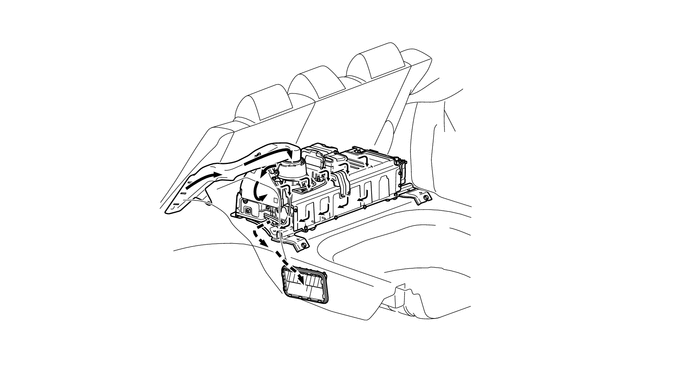
| *1 | Intake Air Duct | *2 | Battery Cooling Blower Assembly |
| *3 | HV Battery Assembly | - | - |

|
Cooling Air Flow | - | - |
Service Plug Grip
By removing the service plug grip before performing any inspection or service, the high-voltage circuit is shut off at the intermediate position of the HV battery, thus ensuring safety during service.
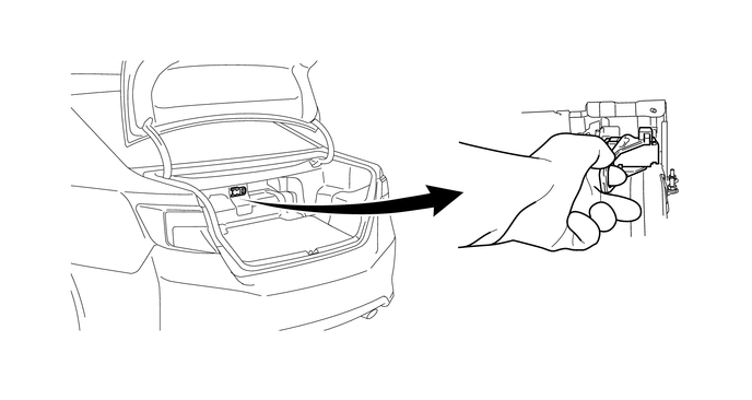
| *1 | Insulated Gloves | *2 | Service Plug Grip |
- CAUTION:
-
A charge remains in the high-voltage capacitor in the inverter with converter assembly after the high-voltage circuits are shut down. When servicing a hybrid vehicle, after the service plug grip is removed, wait at least 10 minutes to allow the capacitor to discharge before beginning work.
- NOTICE:
- ·
The service plug grip should never be removed when the system is in the READY-on state.
·After removing the service plug grip, turning the power switch on (READY) may cause a malfunction. Do not turn the power switch on (READY) unless instructed by the Repair Manual.
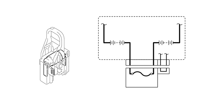
The service plug grip is connected to the middle of the battery module circuit and is used for manually shutting off the high-voltage circuit. This ensures safety during service.
The main fuse for the high-voltage circuit is provided inside of the service plug grip.
An interlock switch has been provided on the service plug grip. When the grip section is unlocked, the interlock switch is turned off and the power management control ECU shuts off the system main relays. However, to ensure safety, make sure to turn the power switch off before removing the service plug grip.
- CAUTION:
-
For further details on how to handle the service plug grip and other safety cautions, refer to the Repair Manual.