THEFT DETERRENT / KEYLESS ENTRY SMART ENTRY AND START SYSTEM DETAILS POWER MANAGEMENT CONTROL ECU
CONSTRUCTION
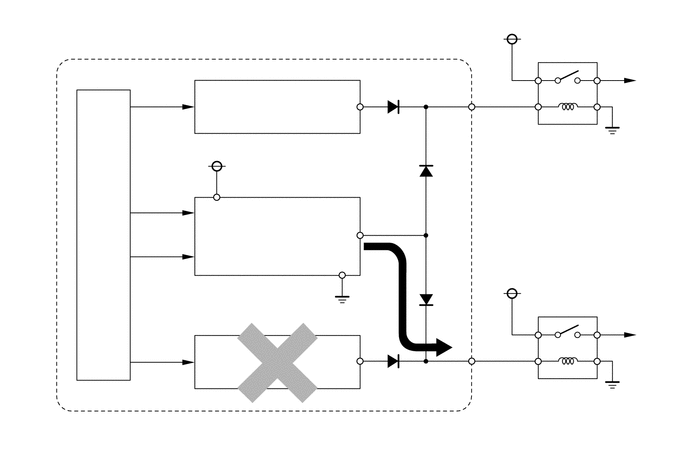
The power management control ECU includes the IG1 relay and IG2 relay actuation circuits, CPU, and hold circuit.
The hold circuit is provided to prevent the power supply to the relays from being cut off when an abnormality occurs in the IG1 relay and/or IG2 relay actuation circuits while driving.
- HINT:
-
The power management control ECU constantly stores the present power source mode in its memory. Therefore, if the power to the power management control ECU is interrupted due to the removal of the battery, the power management control ECU restores the power source after the battery is reconnected.
-
For this reason, if the battery is removed when the power source is in a mode other than off, the power will be restored to the vehicle at the same time the power is restored to the power management control ECU by reconnecting the battery.
-
Therefore, before removing the battery, be sure to turn the power source off.