RM2040EQ
_51
Engine / Hybrid System
_014691
2AR-FXE ENGINE CONTROL
_0074884
INTEGRATION RELAY
G
2AR-FXE ENGINE CONTROL INTEGRATION RELAY INSPECTION
PROCEDURE

 82641
1.INSPECT NO. 1 INTEGRATION RELAY
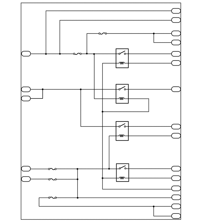
0.823,1.813 1.052,2.01
0.229,0.198
10
false
1A
0.875,1.625 1.031,1.823
0.156,0.198
10
false
8
6.167,0.302 6.427,0.5
0.26,0.198
10
false
1C
6.208,0.125 6.365,0.323
0.156,0.198
10
false
4
6.208,0.469 6.365,0.667
0.156,0.198
10
false
3
6.208,0.917 6.365,1.115
0.156,0.198
10
false
9
6.177,1.26 6.354,1.458
0.177,0.198
10
false
10
6.177,1.823 6.375,2.021
0.198,0.198
10
false
1B
6.167,2.146 6.396,2.344
0.229,0.198
10
false
1C
6.208,1.656 6.313,1.854
0.104,0.198
10
false
1
6.208,1.979 6.313,2.177
0.104,0.198
10
false
7
6.208,2.896 6.313,3.094
0.104,0.198
10
false
1
6.146,3.073 6.365,3.271
0.219,0.198
10
false
1D
6.156,4.396 6.375,4.594
0.219,0.198
10
false
1C
6.208,4.24 6.365,4.438
0.156,0.198
10
false
6
6.156,4.729 6.375,4.927
0.219,0.198
10
false
1E
6.208,4.563 6.365,4.76
0.156,0.198
10
false
1
6.167,5.896 6.385,6.094
0.219,0.198
10
false
1D
6.208,5.729 6.365,5.927
0.156,0.198
10
false
3
6.156,6.229 6.375,6.427
0.219,0.198
10
false
1C
6.208,6.073 6.365,6.271
0.156,0.198
10
false
8
6.156,6.594 6.375,6.792
0.219,0.198
10
false
1E
6.208,6.427 6.365,6.625
0.156,0.198
10
false
2
6.156,6.906 6.375,7.104
0.219,0.198
10
false
1C
6.156,7.229 6.375,7.427
0.219,0.198
10
false
1C
6.156,7.573 6.375,7.729
0.219,0.156
10
false
1C
6.229,6.76 6.385,6.958
0.156,0.198
10
false
5
6.208,7.073 6.365,7.271
0.156,0.198
10
false
2
6.208,7.406 6.365,7.604
0.156,0.198
10
false
1
4.042,2.417 4.719,2.677
0.677,0.26
10
false
EFI MAIN
3.969,3.677 4.74,3.938
0.771,0.26
10
false
EFI MAIN2
4.125,5.01 4.594,5.271
0.469,0.26
10
false
C/OPN
4.229,6.448 4.531,6.708
0.302,0.26
10
false
IG2
2.438,1.979 3.115,2.24
0.677,0.26
10
false
EFI NO. 3
3.333,1.229 4.01,1.49
0.677,0.26
10
false
EFI NO. 2
1.74,6.021 2.083,6.281
0.344,0.26
10
false
IGN
1.75,6.406 2.021,6.667
0.271,0.26
10
false
INJ
1.438,7.052 2.448,7.313
1.01,0.26
10
false
ECU-IG2 NO.3
0.875,2.906 1.031,3.104
0.156,0.198
10
false
7
0.875,3.25 1.031,3.448
0.156,0.198
10
false
6
0.875,5.708 1.031,5.906
0.156,0.198
10
false
1
0.875,6.094 1.031,6.292
0.156,0.198
10
false
3
0.094,0.052 0.302,0.25
0.208,0.198
10
false
*1
0.823,3.083 1.052,3.281
0.229,0.198
10
false
1A
0.823,3.406 1.052,3.604
0.229,0.198
10
false
1A
0.833,5.885 1.063,6.083
0.229,0.198
10
false
1A
0.844,6.26 1.073,6.458
0.229,0.198
10
false
1A
6.167,0.625 6.427,0.823
0.26,0.198
10
false
1C
6.167,1.104 6.438,1.302
0.271,0.198
10
false
1C
6.167,1.427 6.427,1.625
0.26,0.198
10
false
1C
| *1 | No. 1 Integration Relay | - | - |
a.
EFI MAIN Relay:
i.
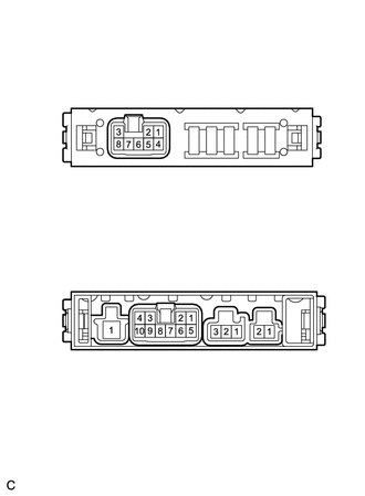
1.052,0.5 1.542,0.792
0.49,0.292
0.74,2.229 1.229,2.521
0.49,0.292
1.313,2.229 1.802,2.521
0.49,0.292
1.906,2.229 2.396,2.521
0.49,0.292
2.438,2.229 2.927,2.521
0.49,0.292
1.177,0.552 1.365,0.813
0.188,0.26
10
false
1A
0.865,2.281 1.052,2.542
0.188,0.26
10
false
1B
1.427,2.281 1.667,2.542
0.24,0.26
10
false
1C
2.01,2.281 2.26,2.542
0.25,0.26
10
false
1D
2.563,2.281 2.75,2.542
0.188,0.26
10
false
1E
0.104,0.052 0.292,0.313
0.188,0.26
10
false
*1
| *1 | No. 1 Integration Relay |
Measure the resistance according to the value(s) in the table below.
- Standard Resistance:
Tester Connection Condition Specified Condition No. 1 integration relay 1B-1 - No. 1 integration relay 1A-8 Auxiliary battery voltage is not applied between terminals 1C-7 and 1E-2 10 kΩ or higher No. 1 integration relay 1B-1 - No. 1 integration relay 1A-8 Auxiliary battery voltage is applied between terminals 1C-7 and 1E-2 Below 1 Ω No. 1 integration relay 1B-1 - No. 1 integration relay 1C-3 No. 1 integration relay 1B-1 - No. 1 integration relay 1C-4 No. 1 integration relay 1B-1 - No. 1 integration relay 1C-9 No. 1 integration relay 1B-1 - No. 1 integration relay 1C-10
If the resistance is not as specified, replace the No. 1 integration relay.
b.
EFI MAIN2 Relay:
i.
1.052,0.5 1.542,0.792
0.49,0.292
0.74,2.229 1.229,2.521
0.49,0.292
1.313,2.229 1.802,2.521
0.49,0.292
1.906,2.229 2.396,2.521
0.49,0.292
2.438,2.229 2.927,2.521
0.49,0.292
1.177,0.552 1.365,0.813
0.188,0.26
10
false
1A
0.865,2.281 1.052,2.542
0.188,0.26
10
false
1B
1.427,2.281 1.667,2.542
0.24,0.26
10
false
1C
2.01,2.281 2.26,2.542
0.25,0.26
10
false
1D
2.563,2.281 2.75,2.542
0.188,0.26
10
false
1E
0.104,0.052 0.292,0.313
0.188,0.26
10
false
*1
| *1 | No. 1 Integration Relay |
Measure the resistance according to the value(s) in the table below.
- Standard Resistance:
Tester Connection Condition Specified Condition No. 1 integration relay 1A-6 - No. 1 integration relay 1D-1 Auxiliary battery voltage is not applied between terminals 1A-8 and 1E-2 10 kΩ or higher No. 1 integration relay 1A-6 - No. 1 integration relay 1D-1 Auxiliary battery voltage is applied between terminals 1A-8 and 1E-2 Below 1 Ω No. 1 integration relay 1A-7 - No. 1 integration relay 1D-1
If the resistance is not as specified, replace the No. 1 integration relay.
c.
IG2 Relay:
i.
1.052,0.5 1.542,0.792
0.49,0.292
0.74,2.229 1.229,2.521
0.49,0.292
1.313,2.229 1.802,2.521
0.49,0.292
1.906,2.229 2.396,2.521
0.49,0.292
2.438,2.229 2.927,2.521
0.49,0.292
1.177,0.552 1.365,0.813
0.188,0.26
10
false
1A
0.865,2.281 1.052,2.542
0.188,0.26
10
false
1B
1.427,2.281 1.667,2.542
0.24,0.26
10
false
1C
2.01,2.281 2.26,2.542
0.25,0.26
10
false
1D
2.563,2.281 2.75,2.542
0.188,0.26
10
false
1E
0.104,0.052 0.292,0.313
0.188,0.26
10
false
*1
| *1 | No. 1 Integration Relay |
Measure the resistance according to the value(s) in the table below.
- Standard Resistance:
Tester Connection Condition Specified Condition No. 1 integration relay 1A-1 - No. 1 integration relay 1D-3 Auxiliary battery voltage is not applied between terminals 1C-8 and 1E-2 10 kΩ or higher No. 1 integration relay 1A-1 - No. 1 integration relay 1D-3 Auxiliary battery voltage is applied between terminals 1C-8 and 1E-2 Below 1 Ω No. 1 integration relay 1A-3 - No. 1 integration relay 1D-3 No. 1 integration relay 1C-1 - No. 1 integration relay 1D-3 No. 1 integration relay 1C-2 - No. 1 integration relay 1D-3 No. 1 integration relay 1C-5 - No. 1 integration relay 1D-3
If the resistance is not as specified, replace the No. 1 integration relay.
d.
C/OPN Relay:
i.
1.052,0.5 1.542,0.792
0.49,0.292
0.74,2.229 1.229,2.521
0.49,0.292
1.313,2.229 1.802,2.521
0.49,0.292
1.906,2.229 2.396,2.521
0.49,0.292
2.438,2.229 2.927,2.521
0.49,0.292
1.177,0.552 1.365,0.813
0.188,0.26
10
false
1A
0.865,2.281 1.052,2.542
0.188,0.26
10
false
1B
1.427,2.281 1.667,2.542
0.24,0.26
10
false
1C
2.01,2.281 2.26,2.542
0.25,0.26
10
false
1D
2.563,2.281 2.75,2.542
0.188,0.26
10
false
1E
0.104,0.052 0.292,0.313
0.188,0.26
10
false
*1
| *1 | No. 1 Integration Relay |
Measure the resistance according to the value(s) in the table below.
- Standard Resistance:
Tester Connection Condition Specified Condition No. 1 integration relay 1A-6 - No. 1 integration relay 1C-6 Auxiliary battery voltage is not applied between terminals 1A-1 and 1E-1 10 kΩ or higher No. 1 integration relay 1A-6 - No. 1 integration relay 1C-6 Auxiliary battery voltage is applied between terminals 1A-1 and 1E-1 Below 1 Ω No. 1 integration relay 1A-7 - No. 1 integration relay 1C-6
If the resistance is not as specified, replace the No. 1 integration relay.