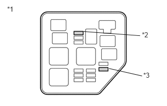
Home › Engine / Hybrid System › HYBRID / BATTERY CONTROL › HYBRID CONTROL SYSTEM › 2012.02–2015.04
RM2040EQ _51 Engine / Hybrid System _014692 HYBRID / BATTERY CONTROL _0074885 HYBRID CONTROL SYSTEM J

HYBRID / BATTERY CONTROL  HYBRID CONTROL SYSTEM  ECU Power Source Circuit  


DESCRIPTION

If the power switch is on (IG), the power management control ECU applies current to the MREL terminal to turn the IGCT relay on. This supplies power to the +B1 and +B2 terminals.

WIRING DIAGRAM
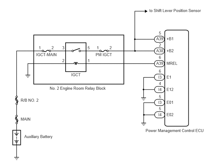
A260348E01
0.841,4.653 1.872,4.823 1.031,0.17 10 Auxiliary Battery 0.715,4.05 1.093,4.192 0.378,0.142 10 MAIN 1.252,1.808 1.998,1.951 0.747,0.142 10 IGCT-MAIN 3.311,1.808 3.912,1.951 0.601,0.142 10 PM IGCT 5.17,0.286 7.03,0.438 1.86,0.152 10 to Shift Lever Position Sensor 1.721,2.983 3.731,3.151 2.01,0.168 10 No. 2 Engine Room Relay Block 5.041,4.447 7.126,4.615 2.085,0.168 10 Power Management Control ECU 2.466,2.514 2.821,2.656 0.355,0.142 10 IGCT 2.153,2.019 2.254,2.161 0.101,0.142 10 2 2.153,1.575 2.254,1.717 0.101,0.142 10 3 3.031,1.575 3.132,1.717 0.101,0.142 10 5 3.346,1.575 3.447,1.717 0.101,0.142 10 1 3.791,1.575 3.892,1.717 0.101,0.142 10 2 1.338,1.575 1.439,1.717 0.101,0.142 10 1 1.783,1.575 1.884,1.717 0.101,0.142 10 2 5.5,1.061 5.601,1.204 0.101,0.142 10 5 5.41,1.264 5.678,1.407 0.267,0.142 10 A39 5.765,1.264 6.044,1.407 0.279,0.142 10 +B1 5.765,1.68 6.044,1.822 0.279,0.142 10 +B2 5.765,2.114 6.183,2.257 0.418,0.142 10 MREL 5.765,2.591 5.954,2.733 0.189,0.142 10 E1 5.765,3.016 6.037,3.158 0.272,0.142 10 E12 5.765,3.469 6.037,3.611 0.272,0.142 10 E01 5.765,3.894 6.037,4.036 0.272,0.142 10 E02 5.5,1.477 5.601,1.619 0.101,0.142 10 2 5.41,1.68 5.678,1.822 0.267,0.142 10 A38 5.5,1.911 5.601,2.054 0.101,0.142 10 6 5.41,2.114 5.678,2.257 0.267,0.142 10 A39 5.5,2.388 5.601,2.53 0.101,0.142 10 6 5.48,2.591 5.62,2.733 0.14,0.142 10 I3 5.5,2.813 5.601,2.955 0.101,0.142 10 4 5.48,3.016 5.62,3.158 0.14,0.142 10 I4 5.5,3.266 5.598,3.408 0.097,0.142 10 5 5.48,3.469 5.62,3.611 0.14,0.142 10 I3 5.5,3.691 5.601,3.833 0.101,0.142 10 5 5.48,3.894 5.62,4.036 0.14,0.142 10 I4 3.031,2.019 3.132,2.161 0.101,0.142 10 1 0.715,3.392 1.385,3.534 0.67,0.142 10 R/B NO. 2

Refer to the wiring diagram for DTC P0A08-264.

See pageEngine / Hybrid System>HYBRID / BATTERY CONTROL>HYBRID CONTROL SYSTEM>P0A08-264

PROCEDURE

1.CHECK POWER MANAGEMENT CONTROL ECU (+B1, +B2 VOLTAGE)
a.

Turn the power switch on (IG).


b.
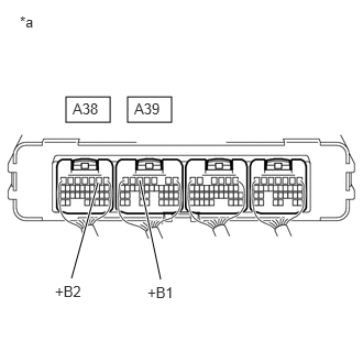
A252924C91
0.625,0.917 1.042,1.156 0.417,0.24 1.208,0.917 1.625,1.156 0.417,0.24 0.677,2.635 0.927,1.729 true 1.521,2.646 1.323,1.708 true 0.688,0.948 0.958,1.115 0.271,0.167 10 false A38 1.271,0.948 1.542,1.115 0.271,0.167 10 false A39 1.396,2.688 1.688,2.844 0.292,0.156 10 false +B1 0.521,2.677 0.875,2.948 0.354,0.271 10 false +B2 0.188,0.125 0.365,0.302 0.177,0.177 10 false *a
*a Component with harness connected
(Power Management Control ECU)


Measure the voltage according to the value(s) in the table below.

Standard Voltage:
Tester Connection Switch Condition Specified Condition
A38-2 (+B2) - Body ground Power switch on (IG) 11 to 14 V
A39-5 (+B1) - Body ground Power switch on (IG) 11 to 14 V


c.

Turn the power switch off.

Result:
Proceed to
OK
NG


OK

2.CHECK HARNESS AND CONNECTOR (POWER MANAGEMENT CONTROL ECU - BODY GROUND)

NG

3.CHECK POWER MANAGEMENT CONTROL ECU (MREL VOLTAGE)
2.CHECK HARNESS AND CONNECTOR (POWER MANAGEMENT CONTROL ECU - BODY GROUND)
a.

Disconnect connector I3 and I4 from the power management control ECU.
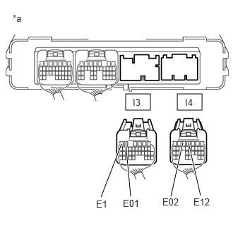

b.
A253458C14
1.854,1.385 2.219,1.625 0.365,0.24 2.615,1.385 2.979,1.625 0.365,0.24 1.792,2.125 1.49,2.906 true 1.854,2.104 1.927,2.896 true 2.698,2.104 2.521,2.896 true 2.781,2.104 2.958,2.885 true 1.958,1.427 2.104,1.594 0.146,0.167 10 false I3 2.729,1.427 2.865,1.594 0.135,0.167 10 false I4 1.417,2.927 1.635,3.094 0.219,0.167 10 false E1 2.396,2.896 2.688,3.063 0.292,0.167 10 false E02 2.854,2.896 3.146,3.063 0.292,0.167 10 false E12 1.813,2.917 2.094,3.083 0.281,0.167 10 false E01 0.188,0.188 0.406,0.354 0.219,0.167 10 false *a
*a Rear view of wire harness connector
(to Power Management Control ECU)


Measure the resistance according to the value(s) in the table below.

Standard Resistance:
Tester Connection Condition Specified Condition
I3-5 (E01) - Body ground Always Below 1 Ω
I3-6 (E1) - Body ground Always Below 1 Ω
I4-4 (E12) - Body ground Always Below 1 Ω
I4-5 (E02) - Body ground Always Below 1 Ω


c.

Connect the power management control ECU connectors.

Result:
Proceed to
OK
NG


OK

NG

REPAIR OR REPLACE HARNESS OR CONNECTOR

3.CHECK POWER MANAGEMENT CONTROL ECU (MREL VOLTAGE)
a.

Turn the power switch on (IG).


b.
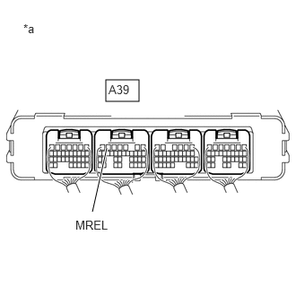
A252924C92
1.229,0.927 1.615,1.177 0.385,0.25 1.24,1.719 1.073,2.458 true 0.271,0.25 0.438,0.406 0.167,0.156 10 false *a 0.875,2.531 1.406,2.885 0.531,0.354 10 false MREL 1.26,0.958 1.531,1.125 0.271,0.167 10 false A39
*a Component with harness connected
(Power Management Control ECU)


Measure the voltage according to the value(s) in the table below.

Standard Voltage:
Tester Connection Switch Condition Specified Condition
A39-6 (MREL) - Body ground Power switch on (IG) 11 to 14 V


Result:
Proceed to
OK
NG


OK

4.CHECK FUSE (PM IGCT)

NG

4.CHECK FUSE (PM IGCT)

Click here

a.

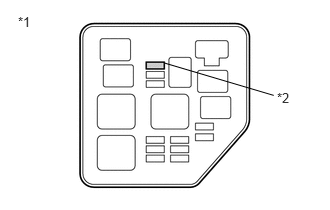
Remove the PM IGCT fuse from the No. 2 engine room relay block.
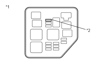

b.
A260347C04
1.719,0.656 2.854,0.99 false 0.188,0.146 0.344,0.302 0.156,0.156 10 false *1 2.885,0.938 3.042,1.094 0.156,0.156 10 false *2
*1 No. 2 Engine Room Relay Block
*2 PM IGCT Fuse


Measure the resistance according to the value(s) in the table below.

Standard Resistance:
Tester Connection Condition Specified Condition
PM IGCT fuse terminals Always Below 1 Ω


c.

Install the PM IGCT fuse.


Result:
Proceed to
OK
NG


OK

5.CHECK FUSE (IGCT-MAIN)

NG

12.REPAIR OR REPLACE HARNESS OR CONNECTOR
5.CHECK FUSE (IGCT-MAIN)

OK

6.INSPECT RELAY (IGCT)

NG

13.CHECK HARNESS AND CONNECTOR (NO. 2 ENGINE ROOM RELAY BLOCK)
6.INSPECT RELAY (IGCT)
a.

Remove the IGCT relay from the No. 2 engine room relay block.
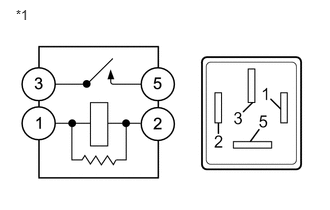

b.
A253297C12
0.165,0.068 0.398,0.266 0.233,0.198 10 *1
*1 IGCT Relay


Measure the resistance according to the value(s) in the table below.
Standard Resistance:
Tester Connection Switch Condition Specified Condition
3 - 5 Auxiliary battery voltage is not applied between terminals 1 and 2 10 kΩ or higher
Auxiliary battery voltage is applied between terminals 1 and 2 Below 1 Ω


Result:
Proceed to
OK
NG


c.

Install the IGCT relay.


OK

7.CHECK HARNESS AND CONNECTOR (POWER MANAGEMENT CONTROL ECU - NO. 2 ENGINE ROOM RELAY BLOCK)

NG

REPLACE RELAY (IGCT)

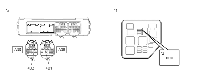
7.CHECK HARNESS AND CONNECTOR (POWER MANAGEMENT CONTROL ECU - NO. 2 ENGINE ROOM RELAY BLOCK)
a.
A260347C05
0.187,0.142 0.343,0.298 0.156,0.156 10 *1 2.885,0.941 3.041,1.097 0.156,0.156 10 *2 1.716,0.657 2.851,0.993 false
*1 No. 2 Engine Room Relay Block
*2 PM IGCT Fuse


Remove the PM IGCT fuse from the No. 2 engine room relay block.

b.

Disconnect connector A38 and A39 from the power management control ECU.


c.

Measure the resistance according to the value(s) in the table below.
A266964C02
0.448,1.698 0.823,1.927 0.375,0.229 2.052,1.698 2.427,1.927 0.375,0.229 1.146,2.354 1.26,1.771 true 1.781,2.354 1.625,1.771 true 0.521,1.719 0.792,1.885 0.271,0.167 10 false A38 2.125,1.719 2.396,1.885 0.271,0.167 10 false A39 0.99,2.396 1.26,2.563 0.271,0.167 10 false +B2 0.208,0.292 0.385,0.458 0.177,0.167 10 false *a 4.146,0.292 4.323,0.458 0.177,0.167 10 false *1 5.844,1.854 6.042,2.052 0.198,0.198 10 false *2 1.656,2.396 1.927,2.563 0.271,0.167 10 false +B1
*1 No. 2 Engine Room Relay Block *2 PM IGCT Fuse
*a Rear view of wire harness connector
(to Power Management Control ECU)
- -


Standard Resistance:
Tester Connection Condition Specified Condition
A39-5 (+B1) - 2 (PM IGCT fuse) Always Below 1 Ω
A38-2 (+B2) - 2 (PM IGCT fuse) Always Below 1 Ω


d.

Install the PM IGCT fuse.


e.

Connect the power management control ECU connectors.

Result:
Proceed to
OK
NG


OK

8.CHECK HARNESS AND CONNECTOR (NO. 2 ENGINE ROOM RELAY BLOCK)

NG

REPAIR OR REPLACE HARNESS OR CONNECTOR

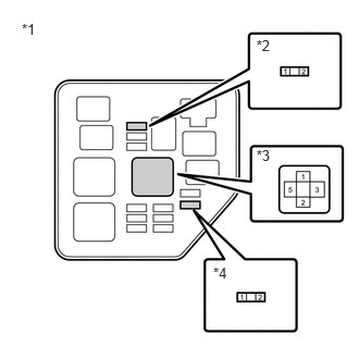
8.CHECK HARNESS AND CONNECTOR (NO. 2 ENGINE ROOM RELAY BLOCK)
a.
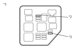
A260385C03
1.719,0.646 2.885,0.74 false 2.198,1.427 2.885,1.573 false 0.146,0.104 0.313,0.271 0.167,0.167 10 false *1 2.917,0.635 3.198,0.938 0.281,0.302 10 false *2 2.917,1.5 3.125,1.833 0.208,0.333 10 false *3
*1 No. 2 Engine Room Relay Block
*2 PM IGCT Fuse
*3 IGCT-MAIN Fuse


Remove the IGCT-MAIN fuse and PM IGCT fuse from the No. 2 engine room relay block.
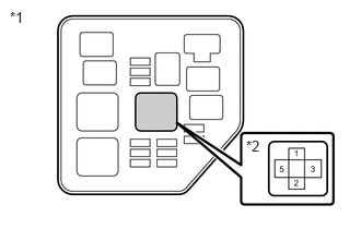

b.

Remove the IGCT relay from the No. 2 engine room relay block.


c.
A260386C03
0.209,0.202 0.393,0.367 0.184,0.166 10 *1 2.455,0.351 2.639,0.516 0.184,0.166 10 *2 2.455,1.405 2.639,1.571 0.184,0.166 10 *3 2.042,2.528 2.226,2.693 0.184,0.166 10 *4
*1 No. 2 Engine Room Relay Block
*2 PM IGCT Fuse
*3 IGCT Relay
*4 IGCT-MAIN Fuse


Measure the resistance according to the value(s) in the table below.
Standard Resistance:
Tester Connection Condition Specified Condition
3 (IGCT relay) - 2 (IGCT-MAIN fuse) Always Below 1 Ω
5 (IGCT relay) - 1 (PM IGCT fuse) Always Below 1 Ω


d.

Install the IGCT-MAIN fuse and PM IGCT fuse.


e.

Install the IGCT relay.


Result:
Proceed to
OK
NG


OK

9.CHECK HARNESS AND CONNECTOR (POWER MANAGEMENT CONTROL ECU - NO. 2 ENGINE ROOM RELAY BLOCK)

NG

REPAIR OR REPLACE HARNESS OR CONNECTOR

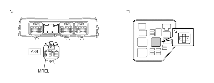
9.CHECK HARNESS AND CONNECTOR (POWER MANAGEMENT CONTROL ECU - NO. 2 ENGINE ROOM RELAY BLOCK)
a.

Remove the IGCT relay from the No. 2 engine room relay block.


b.

Disconnect connector A39 from the power management control ECU.


c.

Measure the resistance according to the value(s) in the table below.

A266965C02
0.969,1.625 1.344,1.854 0.375,0.229 1.479,2.281 1.583,1.708 true 1.031,1.656 1.313,1.854 0.281,0.198 10 false A39 1.271,2.313 1.74,2.531 0.469,0.219 10 false MREL 0.323,0.302 0.5,0.469 0.177,0.167 10 false *a 4.229,0.302 4.406,0.469 0.177,0.167 10 false *1 5.813,0.969 6,1.198 0.188,0.229 10 false *2
*1 No. 2 Engine Room Relay Block *2 IGCT Relay
*a Rear view of wire harness connector
(to Power Management Control ECU)
- -


Standard Resistance:
Tester Connection Condition Specified Condition
A39-6 (MREL) - 1 (IGCT relay) Always Below 1 Ω
A39-6 (MREL) or 1 (IGCT relay) - Body ground and other terminals Always 10 kΩ or higher


d.

Install the IGCT relay.


e.

Connect the power management control ECU connectors.


Result:
Proceed to
OK
NG


OK

10.CHECK HARNESS AND CONNECTOR (NO. 2 ENGINE ROOM RELAY BLOCK - BODY GROUND)

NG

REPAIR OR REPLACE HARNESS OR CONNECTOR

10.CHECK HARNESS AND CONNECTOR (NO. 2 ENGINE ROOM RELAY BLOCK - BODY GROUND)
a.

Remove the IGCT relay from the No. 2 engine room relay block.


b.
A259798C05
0.094,0.083 0.323,0.313 0.229,0.229 10 false *1 2.344,1.313 2.531,1.615 0.188,0.302 10 false *2
*1 No. 2 Engine Room Relay Block
*2 IGCT Relay


Measure the resistance according to the value(s) in the table below.

Standard Resistance:
Tester Connection Condition Specified Condition
2 (IGCT relay) - Body ground Always Below 1 Ω


c.

Install the IGCT relay.

Result:
Proceed to
OK
NG


OK

11.CHECK HARNESS AND CONNECTOR (ENGINE ROOM RELAY BLOCK AND JUNCTION BLOCK ASSEMBLY - NO. 2 ENGINE ROOM RELAY BLOCK)

NG

REPAIR OR REPLACE HARNESS OR CONNECTOR

11.CHECK HARNESS AND CONNECTOR (ENGINE ROOM RELAY BLOCK AND JUNCTION BLOCK ASSEMBLY - NO. 2 ENGINE ROOM RELAY BLOCK)
a.

Remove the IGCT-MAIN fuse from the No. 2 engine room relay block.


b.

Disconnect AMD terminal from the engine room relay block and junction block assembly.


c.

Measure the resistance according to the value(s) in the table below.

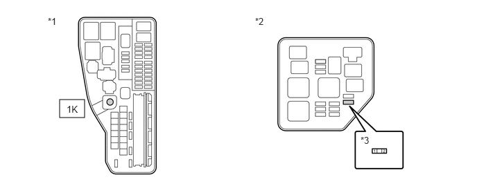
A260388C03
0.896,1.5 1.271,1.771 0.375,0.271 1,1.563 1.208,1.74 0.208,0.177 10 false 1K 0.719,0.24 0.896,0.406 0.177,0.167 10 false *1 3.833,0.24 4.01,0.406 0.177,0.167 10 false *2 5.417,2.031 5.594,2.198 0.177,0.167 10 false *3
*1 Engine Room Relay Block and Junction Block Assembly *2 No. 2 Engine Room Relay Block
*3 IGCT-MAIN Fuse - -


Standard Resistance:
Tester Connection Condition Specified Condition
1K-1 (AMD) - 1 (IGCT-MAIN fuse) Always Below 1 Ω


d.

Install the IGCT-MAIN fuse.


e.

Connect AMD terminal.


Result:
Proceed to
OK
NG


OK

NG

14.CHECK FUSIBLE LINK BLOCK ASSEMBLY (R/B NO. 2)
12.REPAIR OR REPLACE HARNESS OR CONNECTOR
a.

Disconnect connector E11 from the shift lever position sensor.
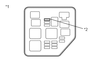

b.
A260347C06
0.187,0.142 0.343,0.298 0.156,0.156 10 *1 2.885,0.941 3.041,1.097 0.156,0.156 10 *2 1.716,0.657 2.851,0.993 false
*1 No. 2 Engine Room Relay Block
*2 PM IGCT Fuse


Remove the PM IGCT fuse from the No. 2 engine room relay block.


c.

Disconnect connectors A38 and A39 from the power management control ECU.


d.

Measure the resistance according to the value(s) in the table below.
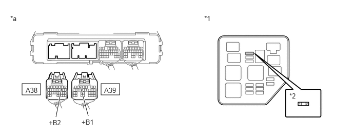
A266964C03
0.448,1.698 0.823,1.927 0.375,0.229 2.052,1.698 2.427,1.927 0.375,0.229 1.135,2.375 1.25,1.792 true 1.792,2.354 1.635,1.771 true 0.521,1.75 0.792,1.917 0.271,0.167 10 false A38 2.115,1.75 2.385,1.917 0.271,0.167 10 false A39 0.99,2.406 1.26,2.573 0.271,0.167 10 false +B2 0.208,0.292 0.385,0.458 0.177,0.167 10 false *a 4.146,0.292 4.323,0.458 0.177,0.167 10 false *1 5.875,1.865 6.052,2.031 0.177,0.167 10 false *2 1.656,2.396 1.927,2.563 0.271,0.167 10 false +B1
*1 No. 2 Engine Room Relay Block *2 PM IGCT Fuse
*a Rear view of wire harness connector
(to Power Management Control ECU)
- -


Standard Resistance:
Tester Connection Condition Specified Condition
A39-5 (+B1) or 2 (PM IGCT fuse) - Body ground and other terminals Always 10 kΩ or higher
A38-2 (+B2) or 2 (PM IGCT fuse) - Body ground and other terminals Always 10 kΩ or higher


e.

Install the PM IGCT fuse.


f.

Connect the shift lever position sensor connector.


g.

Connect the power management control ECU connectors.


Result:
Proceed to
OK
NG


OK

REPLACE FUSE (PM IGCT)

NG

15.REPAIR OR REPLACE HARNESS OR CONNECTOR
13.CHECK HARNESS AND CONNECTOR (NO. 2 ENGINE ROOM RELAY BLOCK)
a.
A260385C04
0.148,0.107 0.311,0.271 0.163,0.163 10 *1 2.921,0.64 3.084,0.803 0.163,0.163 10 *2 2.95,1.474 3.113,1.637 0.163,0.163 10 *3 1.721,0.65 2.884,0.736 false 2.242,1.412 2.924,1.567 false
*1 No. 2 Engine Room Relay Block
*2 PM IGCT Fuse
*3 IGCT-MAIN Fuse


Remove the IGCT-MAIN fuse and PM IGCT fuse from the No. 2 engine room relay block.
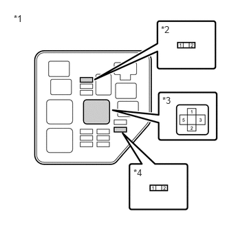

b.

Remove the IGCT relay from the No. 2 engine room relay block.


c.
A260386C04
0.208,0.198 0.396,0.365 0.188,0.167 10 false *1 2.438,0.365 2.625,0.583 0.188,0.219 10 false *2 2.458,1.438 2.656,1.677 0.198,0.24 10 false *3 2.021,2.531 2.208,2.74 0.188,0.208 10 false *4
*1 No. 2 Engine Room Relay Block
*2 PM IGCT Fuse
*3 IGCT Relay
*4 IGCT-MAIN Fuse


Measure the resistance according to the value(s) in the table below.

Standard Resistance:
Tester Connection Condition Specified Condition
3 (IGCT relay) or 2 (IGCT-MAIN fuse) - Body ground and other terminals Always 10 kΩ or higher
5 (IGCT relay) or 1 (PM IGCT fuse) - Body ground and other terminals Always 10 kΩ or higher


d.

Install the IGCT-MAIN fuse and PM IGCT fuse.


e.

Install the IGCT relay.


Result:
Proceed to
OK
NG


OK

REPLACE FUSE (IGCT-MAIN)

NG

16.REPAIR OR REPLACE HARNESS OR CONNECTOR
14.CHECK FUSIBLE LINK BLOCK ASSEMBLY (R/B NO. 2)
a.

Check the fusible link block assembly (R/B NO. 2) in the engine room relay block and junction block assembly for improper installation.

OK:

The fusible link is installed securely.


b.

Remove the fusible link block assembly from the engine room relay block and junction block assembly.
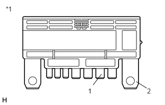

c.
A258447C05
0.12,0.103 0.379,0.315 0.258,0.212 10 *1 3.065,1.816 3.221,1.972 0.156,0.156 10 2 2.838,1.699 3.056,1.836 false 1.833,1.816 1.99,1.972 0.156,0.156 10 1 2.114,1.544 1.938,1.77 false
*1 Fusible Link Block Assembly


Measure the resistance according to the value(s) in the table below.

Standard Resistance:
Tester Connection Condition Specified Condition
Fusible link block assembly 1 - 2 terminals (R/B NO. 2) Always Below 1 Ω


d.

Install the fusible link block assembly.


Result:
Proceed to
OK
NG


OK

REPAIR OR REPLACE HARNESS OR CONNECTOR

NG

REPLACE FUSIBLE LINK BLOCK ASSEMBLY (R/B NO. 2)

15.REPAIR OR REPLACE HARNESS OR CONNECTOR
Result:
Proceed to
NEXT


NEXT

REPLACE FUSE (PM IGCT)

16.REPAIR OR REPLACE HARNESS OR CONNECTOR
Result:
Proceed to
NEXT


NEXT

REPLACE FUSE (IGCT-MAIN)